Model 2929 Scaler Technical Manual Section 3
Ludlum Measurements, Inc. Page 3-1 January 2016
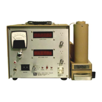
Controls and Functions
Front Panel
High Voltage:
a 10-turn potentiometer control for adjusting HV from 200
V to 2500 V. It provides a linear adjustment of the detector voltage supply.
Changing the detector voltage will cause the detector gain to change. A
linear change in voltage will cause an exponential change in detector gain.
The instrument will support 60-megohm scintillation loads to 1500 V.
HV Meter: a 6.4 cm (2.5 in.) panel meter displaying the high-voltage setting
continuously.
HV: a 10-turn dial used to adjust the detector high voltage.
ON/OFF: a toggle switch used to apply power to the instrument when in the
“ON” position.
Count Lamp: a red light indicating that the scaler is in the count cycle.
Count Switch: resets and starts the counting cycle. This switch will also
reset the two counters when depressed.
HOLD Switch: stops the count cycle without resetting the scaler display.
The counters will hold the value present at the time this button is depressed.
Minutes: a two-decade thumb-wheel switch used for presetting count time.
This switch is used in conjunction with the multiplier switch.
Multiplier: a rotary switch allowing selection of count time mulitpliers of
0.1, 1, 10 or an EXT position for timing using external clock sources.
Detector Input Connection: a series “C” coaxial connector used to supply
the detector with its bias voltage and also to return the signal from the
detector. (Other connectors are available upon request.)
Sectio
3
 Loading...