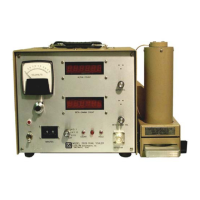
Model 2929 Scaler Technical Manual Section 6
Ludlum Measurements, Inc. Page 6-2 January 2016
Adjust the GAIN control located internally and to the right-hand
side of the instrument for a positive pulse amplitude of 200 mV (at
the AMP OUT connector).
This completes the amplifier gain calibration. The optimum amplifier
gain should be approximately 20.
Apply a negative pulse of 200 mV amplitude.
Attach an oscilloscope probe to pin 7 of U5 ad adjust B-G THS
WIDTH (R6) for a five-microsecond wide negative 5 V pulse.
Move the oscilloscope to pin 9 of U6 and apply a negative pulse of
4 mV amplitude.
Adjust B-G THS (R3) until negative 5-volt pulses appear.
Apply a negative pulse of 50 mV amplitude and adjust B-G WIN
(R2) until negative 5-volt pulses just disapper.
Apply a negative pulse of 175 mV amplitude and adjust ALPHA
THS (R4) until a 5-volt positive pulse appears at pin 6 of U6.
High Voltage Power Supply
With a high-voltage meter of at least 1000 megohm input
impedance, adjust the front-panel HV control for 1000 Vdc at the
detector connector.
Adjust R6 for a front-panel meter reading of 1 kV.
NOTE: If adjustment is necessary, a 10-pin extender board will be required.
With no detector attached, turn the HV dial to maximum (fully
clockwise) and adjust R13 for 1500 V. (Higher limits may be
necessary, depending upon the type of detector being used.
High Voltage Adjustment Procedures
High Voltage: Selection of an operating voltage is determined by the plateau
method. With this method, a graph of high-voltage settings versus counts
received from each channel is generated (source counts and background
counts). LMI uses
239
Pu as the alpha source; and
99
Tc or
14
C as beta sources.

 Loading...