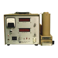
Model 2929 Scaler Technical Manual Section 7
Ludlum Measurements, Inc. Page 7-1 January 2016
Data Output
Function Identification
PIN FUNCTION
1 Count Complete
2 Printer Ready
3 Load Printer
4 Printer Clock
5 Ground
6 Count
7 Hold
8 +5 Vdc
9 Alpha Pulse Out
10 Beta/Gamma Pulse Out
11 Blanking
12 Bit 1
13 Bit 2
14 Bit 3
15 Bit 4
Function Source
All functions are from Model 2929 to accessory except:
PIN 2 Printer Ready
PIN 6 Count
PIN 7 Hold
Output Signals
Output signals are CMOS with LO = GROUND and HI = VOLTAGE
on Pin 8.
Pin 2 Printer Ready: Signal should be of the same voltage swing as the
signals from the Model 2929.
Sectio
7

 Loading...