Model 2929 Scaler Technical Manual Section 7
Ludlum Measurements, Inc. Page 7-2 January 2016
6 Count: Signal should be pulled low to start counting.
Pin 7 Hold: Signal should be pulled low to stop counting.
Removing Data from the Model 2929
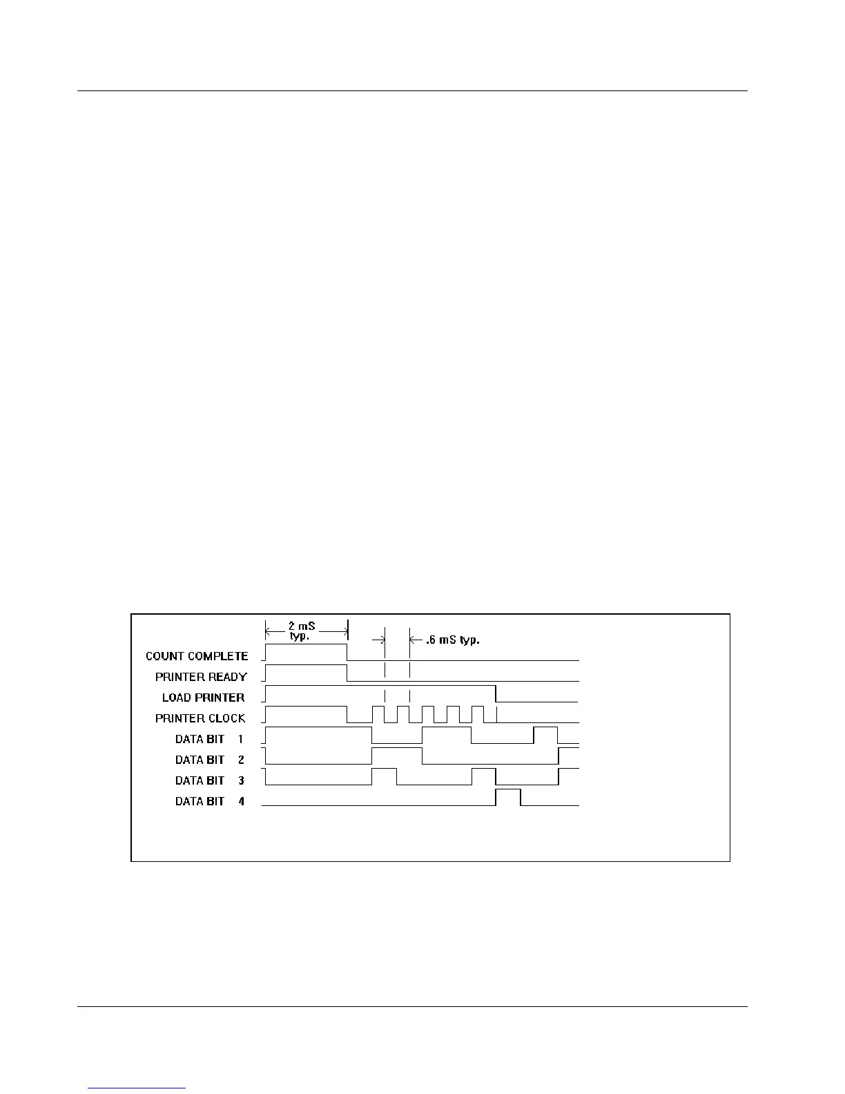
When the Model 2929 has timed out and counting stops, a HI pulse appears
on pin 1 (count complete). This pulse is approximately 2 milliseconds wide
and is used to signal the accessory unit that data is ready to be transmitted.
When the accessory unit is ready to accept the data, Pin 2 (printer ready) is
pulsed HI for a minimum of 2 milliseconds. When this Pin goes LO, data is
unloaded from the Model 2929 as follows:
The most significant digit appears first. This is valid at the negative eduge of
the first clock pulse and position continues until all digits have been read out.
At this time, Pin 3 (load printer) goes LO, signaling completion of data
transfer.
NOTE: Count Complete (Pin 1) and Printer Ready (Pin 2) are tied together.
The data is presented as BCD data on Pins 12 (BIT 1), 13 (BIT 2), 14 (BIT
3), and (BIT 4).
Figure 1
 Loading...