3-10
CDA3000 Operation Manual
3 Installation
3.7 Control
connections
Step Action Comment
1
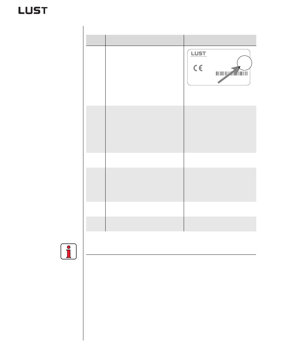
Check whether your inverter module is
fitted
a modified software package
(>V100.x)
(standard software = Vx.xx-xx)
If this is the case, the control terminal
assignment is different. Please
contact your project engineer with
regard to wiring and commissioning!!
Position of software name plate see
section 3.1 Page 3-2
2
Check whether you already have a
S
MARTCARD or a DRIVEMANAGER data
set with a complete device setup.
If this is the case, the control terminal
assignment is different. Please
contact your project engineer to obtain
the terminal assignment!
Bulk customers
For details of how to load the data
set into the inverter module refer to
section 4.6.
3
Choose a terminal assignment.
see 3.7.1 “Choice of terminal
assignment”
4
Wire the control terminals with
shielded cables.
The only essential signals are the
ENPO signals and a start signal
(STR or STL).
Ground the cable shields over a
wide area at both ends.
Wire cross-section maximum
1.5 mm² or two cores per terminal
each 0.5 mm²
5
Keep all contacts open
(inputs inactive).
6
Check all connections again!
Continue with commissioning in
section 4.
Note the following points:
• Always wire the control terminals with shielded cables.
• Lay the control cables separately from the mains lead and motor
cable.
• The CDA3000 Application Manual presents more drive solutions.
• For all shielded connections a cable type with double copper
braiding with 60-70 % coverage must be used.
ANTRIEBSTECHNIK
D- 35633 Lahnau
Type: CDA32.004,C1.0
Software: V
C1D1
CS:
Data Set:
SN.: 99120442
1xx.x
 Loading...
