Page 278
REPAIR INSTRUCTIONS
Coolant Conditioner Installation
Refer to Figure 305.
1. Position a check valve assembly (3) in the
coolant conditioner head assembly (2). The
ball end of the check valve must be inserted
first.
2. Position an O-ring (4) in the O-ring recess of
the head assembly.
3. Install the head assembly (2) on the
thermostat housing (5) and secure with
capscrews (1).
4. Tighten the capscrews to the specified
torque, 15 lb-ft (20 N•m), using torque
wrench J 24406, or equivalent.
5. Apply a light film of engine coolant on the
face of the coolant conditioner filter gasket
seal.
6. Install the coolant conditioner filter element
(14). Turn the coolant conditioner filter one
full turn after the gasket contacts base. Use
tool J 24783 to tighten.
Fuel Filter Adapter Assembly
Installation
[231 PB]
Refer to Figure 306 and Figure 307.
1. Install the fuel filter adapter (1) to the air inlet
manifold (7).
2. Install the three capscrews (4) and tighten to
the specified torque, 35 lb-ft (48 N•m).
3. Install the three fuel lines to the fittings
(2, 3 and 5) and tighten to the specified
torque, 25 lb-ft (34 N•m).
306
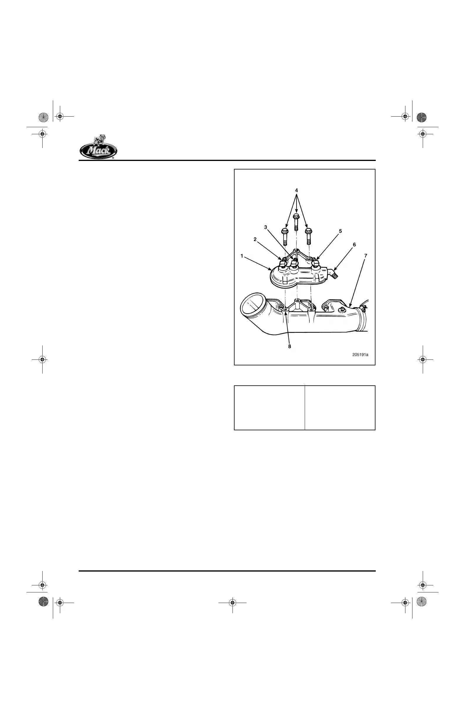
Figure 306 — Fuel Filter Adapter Assembly Installation
with Two-Piece Air Inlet Manifold
1. Fuel Filter Adapter
Assembly
2. Secondary Filter Fitting
(Out)
3. Secondary Filter Fitting
(In)
4. Capscrews
5. Primary Filter Fitting
(Out)
6. Primary Filter Fitting (In)
7. Air Inlet Manifold
8. Mounting Flange
5_106_00.bk Page 278 Friday, August 4, 2000 11:17 AM
BDC for engine manuals and specs
https://barringtondieselclub.co.za/