18
FLAG IN
BANK
+5V
DGND
MONO IN
AGND
RIGHT OUT
LEFT OUT
POT1
POT2
CLIP_LED
N/C
BIT 0
BIT 1
BIT 2
BIT 3
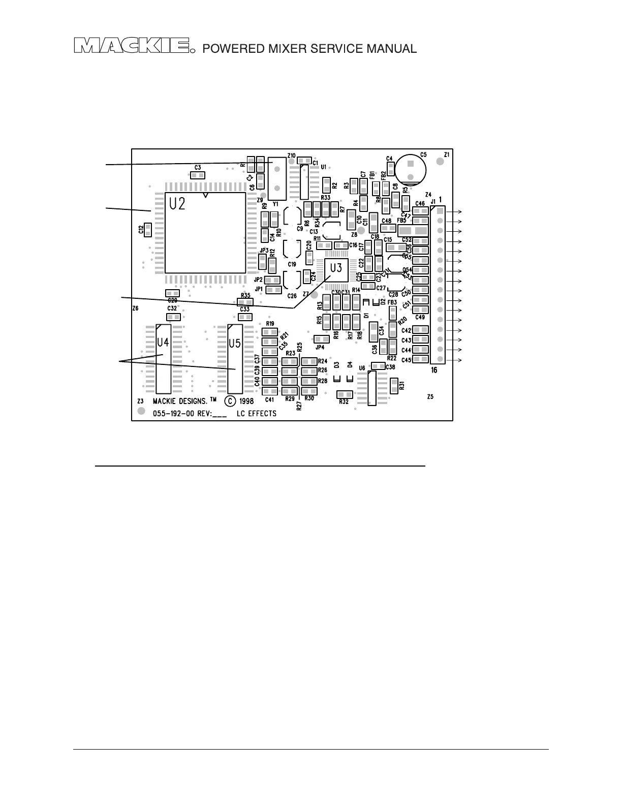
EFX overview
The EFX circuit board schematics and pcb layouts are shown in chapter 192.
The circuit is made from the following main elements: Clock, CODEC, DSP and SRAM
PART NO. DESCRIPTION VALUE REF
080-088-00 IC, ADSP-2163 U2
315-017-00 CRYSTAL, 24.576 MHZ 24.576 Y1
325-027-03 IC, SMD, DUAL D F/F 74HC74A U6
325-071-03 IC, HEX, INV, SMD 74HCU04 U1
329-042-03 IC, AD1819 QFP AD1819 U3
329-047-03 IC, 32KX8 SRAM 20nS 7C256-20 U4-5
INTEGRATED CIRCUITS
EFX OVERVIEW
The CODEC receives a mono analog input from the mixer circuit board and converts it
into a digital signal. The CODEC also receives analog control signals from the two
Parameter pots, converts this to digital and sends a combined digital signal to the DSP.
The DSP and the two SRAM ICs, form a powerful DSP system. The DSP receives the digital
data from the CODEC as well as the direct control signals from the rotary encoder and
the EFX WIDE switch. The DSP programing selects and performs the appropriate DSP
function on the signal data, and sends it back to the CODEC.
The CODEC converts the incoming digital signals to two analog outputs. For DELAY and
PHASER effects, these are identical signals. For other effect selections, these have subtle
differences. For stereo mixers, these are sent to the main left and right mix, and also
summed to the monitor mix. For mono mixers, they are summed and sent to the main
and monitor mixes.
CLOCK Y1
DSP IC U2
CODEC IC U3
SRAM U4, U5
Rotary
Encoder
Parameter pots
Analog outputs
Analog input
WIDE switch
Bypass switch