Owner’s Manual
9
Owner’s Manual
Large Club System
SIG/OL
FRONT LED PHASE
FR OUTPUT
U
+6dB-6dB
160Hz80Hz
120Hz
INPUT HIGH PASS
OUT
FULL RANGE
OUT
NORMAL
INVERT
FLAT
DEEP
PUNCH
VARIABLE
ON
OFF
STEREO
MONO
A
HIGH PASS MODE
A
B
B
SIG/OL
FRONT LED PHASE
FR OUTPUT
U
+6dB-6dB
160Hz80Hz
120Hz
INPUT HIGH PASS
OUT
FULL RANGE
OUT
NORMAL
INVERT
FLAT
DEEP
PUNCH
VARIABLE
ON
OFF
STEREO
MONO
A
HIGH PASS MODE
A
B
B
SIG/OL
FRONT LED PHASE
FR OUTPUT
U
+6dB-6dB
160Hz80Hz
120Hz
INPUT HIGH PASS
OUT
FULL RANGE
OUT
NORMAL
INVERT
FLAT
DEEP
PUNCH
VARIABLE
ON
OFF
STEREO
MONO
A
HIGH PASS MODE
A
B
B
SIG/OL
FRONT LED PHASE
FR OUTPUT
U
+6dB-6dB
160Hz80Hz
120Hz
INPUT HIGH PASS
OUT
FULL RANGE
OUT
NORMAL
INVERT
FLAT
DEEP
PUNCH
VARIABLE
ON
OFF
STEREO
MONO
A
HIGH PASS MODE
A
B
B
LINE
MIC
LINE
U U
MAX
LINE MIC
U
MAX
CH1
CH2 MAIN
THRU
OVERLOADPAIR LINK
MUSIC
DUCKING
FEEDBACK
ELIMINATOR
OUTDOOR
MODE
VOICING MODES
FRONT
LED
MUSIC
MON
LIVE
CLUB
-
∞
MAXMIN MIN
CLUB
LIVE
VOICING MODES
MUSIC
MON
GAIN VOLUME
GAIN
LINE
MIC
LINE
U U
MAX
LINE MIC
U
MAX
CH1
CH2 MAIN
THRU
OVERLOADPAIR LINK
MUSIC
DUCKING
FEEDBACK
ELIMINATOR
OUTDOOR
MODE
VOICING MODES
FRONT
LED
MUSIC
MON
LIVE
CLUB
-
∞
MAXMIN MIN
CLUB
LIVE
VOICING MODES
MUSIC
MON
GAIN VOLUME
GAIN
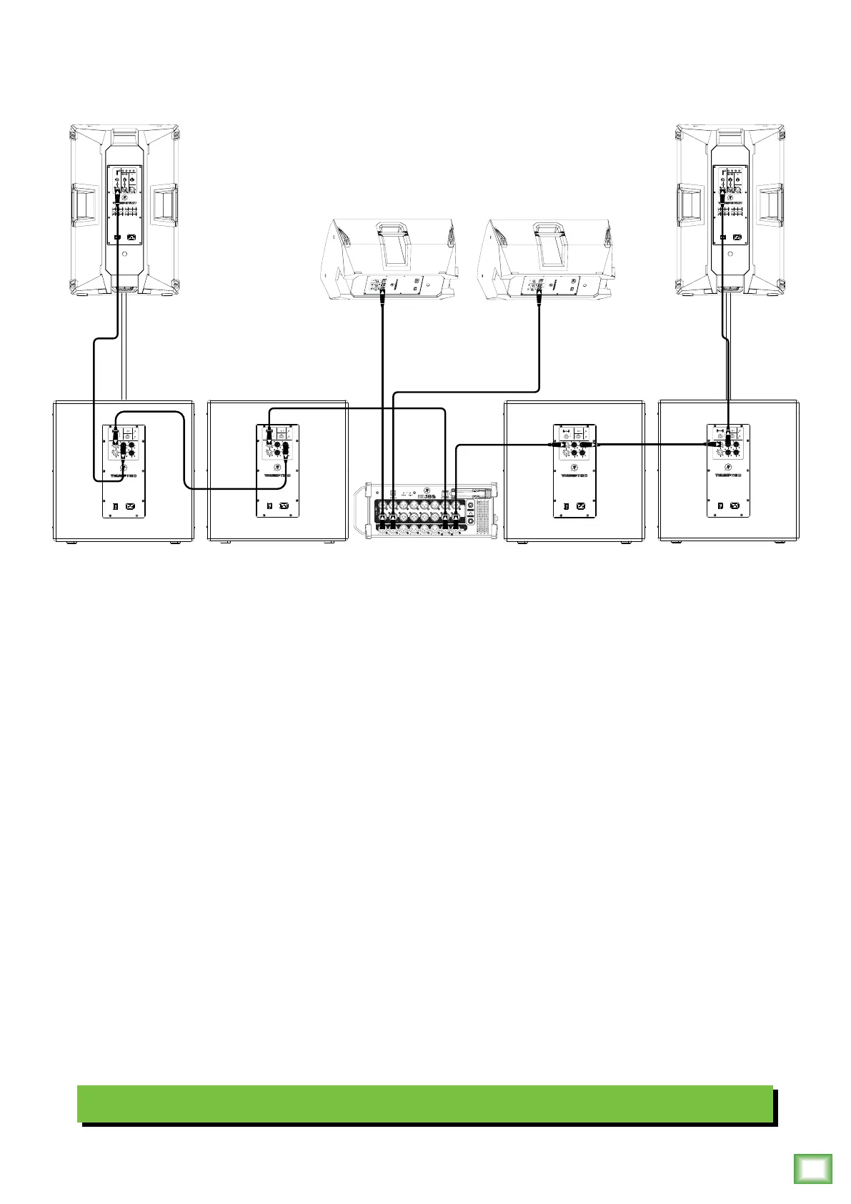
Hookup Diagrams continued…
Here’s how to set up a large club system. In this example, the L/R outputs of a DL6S mixer are connected directly
to the channel A inputs of a pair of Thump8S subwoofers. The Full Range Out of each subwoofer is then connected
to the inputs of an additional pair of Thump8S subwoofers.
From here, the High Pass Out of the two outer Thump8S subwoofers are connected directly to the inputs
of a set of Thump25XT loudspeakers. Then set the subwoofer’s High Pass Mode to Deep and the voicing
mode of both loudspeakers to live or club. Talk about beefy low end!
Outputs and 2 from the mixer may be used as aux sends; these are connected directly to the channel inputs of a pair
of Thump25 loudspeakers to be used as monitors for the band. The gain knob on all Thump loudspeakers in this example
should be set to Line. Lastly, all Mic/Line switches should be disengaged [Line]. Keep in mind that these “MIC” and “LINE”
markings are for reference only and may need to be raised or lowered.