12
Figure 11
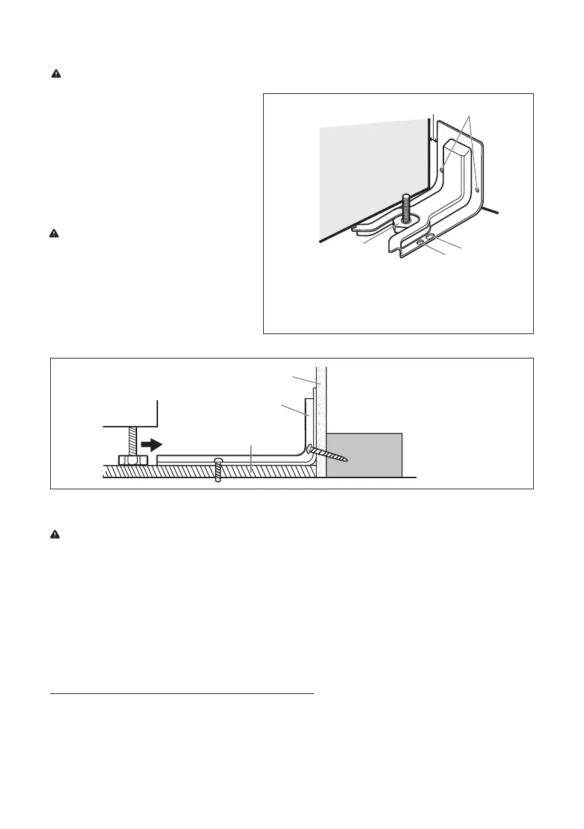
3� Use the bracket as a template to mark
the position of the holes you will use
to secure it. Drill two 1/8” (3mm) pilot
holes at the marks.
4� Using the screws provided, secure
the anti-tip bracket to the floor�
(Refer to Figure 11 for 3 different
securing options�)
HOW TO CONNECT GAS LINE
WARNING: Explosion Hazard
• Use a new CSA International approved gas supply line�
• Install a shut-off valve�
• Securely tighten all gas connection�
• If connected to LP, have a qualified technician make sure gas pressure does not exceed 14” (36cm) water
column�
• Examples of a qualified technician include: licensed heating personnel, authorized gas company personnel,
and authorized service personnel�
• Failure to do so can result in death, explosion or fire�
How to Install Typical Flexible Connection (Refer to Figure 12�)
1� Apply pipe-joint compound made for use with NG (natural gas) to the male threads of the adapter�
2� Insert adapter into outlet of the gas pressure regulator, and then tighten using two 10” adjustable wrenches�
Be sure flow arrow on regulator is pointing up toward the range gas inlet pipe�
Figure 10
a
b
d
c
e
a.
Distance from
Adjacent Cabinet (3/8"
to 1/2" [0.95 to 1.27 cm])
b. Wall Holes
c. Concrete Floor Holes
d. Wood Floor Holes
e. Rear Range Foot
5� Using the screws provided, secure the
NOTE: For concrete construction 1/4" x
1-1/2" Lag Bolts and 1/2" O.D. anchors are
required.
anti-tip bracket to the floor
or
wall
� (Refer to Figure 11 for 3
different securing options�)
a
b
c
a. Wall
b. Anti-tip
Bracket
c. Floor
depth of the overhang plus an additional 3/8" to 1/2". (Refer to Figure 10.)
NOTE: The anti-tip bracket can be installed on either side of the opening (left or right).
 Loading...