18
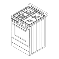
NOTE: The triple burner has only two injectors, one injector mounted in the center and another mounted below
the cover plate. To access the second injector, remove the two screws and the cover plate.
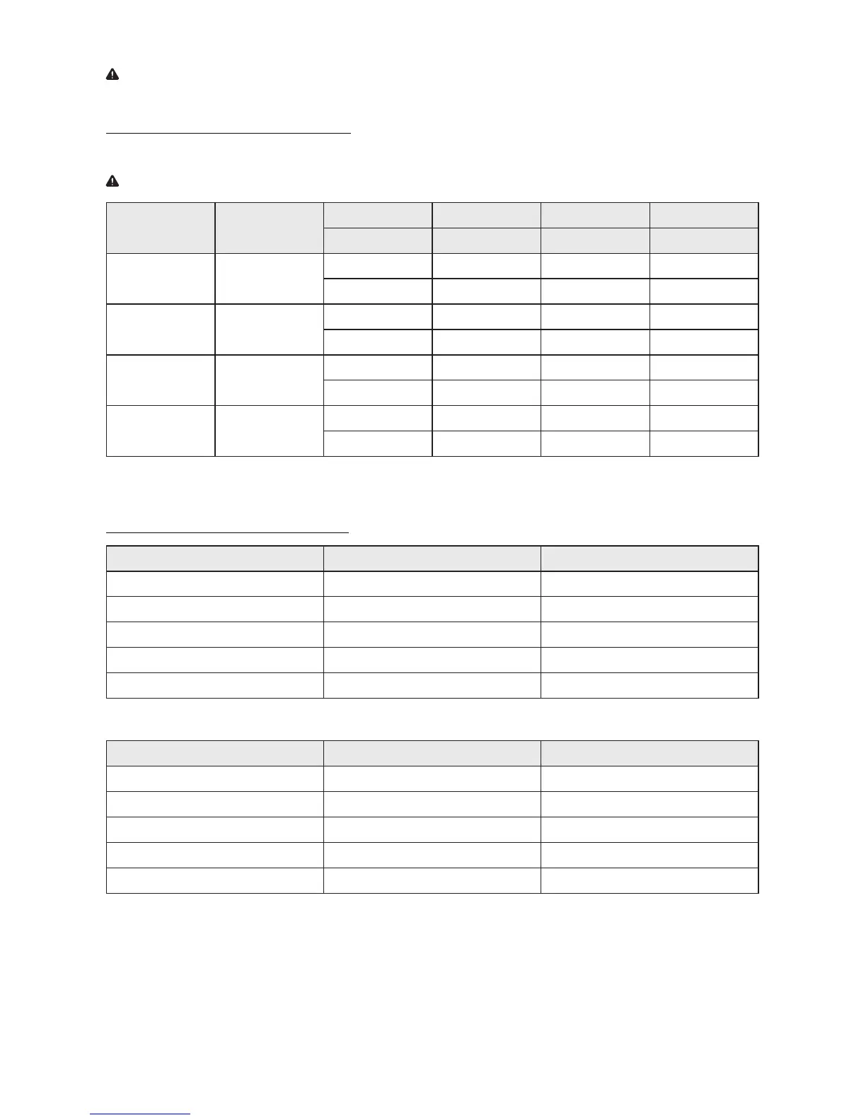
24” Burner and Orifice Characteristic Table
Refer to the following chart for correct gas orifice spud placement.
IMPORTANT: Save the orifices removed from the appliance for future use.
Burner Position
Orifice Gas Pressure Rate
Diam. (mm) Type [i.w.c] [BTU/h]
Auxiliary Front R
0.9 NG 4” 5000
0.58 LP (Propane) 10” 5000
Semi-Rapid Rear L
1.17 NG 4” 6859
0.75 LP (Propane) 10” 6859
Triple Front L
0.93 + 1.82 NG 4” 17357
1.14 + 0.56 LP (Propane) 10” 15000
Rapid Raer R
1.6 NG 4” 6859
1.03 LP (Propane) 10” 6859
24” SERIES OF PRODUCTS
Gas Type: Natural Gas 4” Test Point Pressure
Burner Injector Size (mm) Burner Rating (BTU)
Large 0.99 mm x 5 17400
Small 1.29 mm 6900
Tiny 1.10 mm 5000
Top Burner 1.40 mm 7900
Bottom Burner 1.70 mm 10700
Gas Type: LPG 10” Test Point Pressure
Burner Injector Size (mm) Burner Rating (BTU)
Large 0.56 mm x 5 15000
Small 0.80 mm 6500
Tiny 0.70 mm 5000
Top Burner 0.85 mm 7900
Bottom Burner 1.10 mm 10800

 Loading...