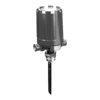
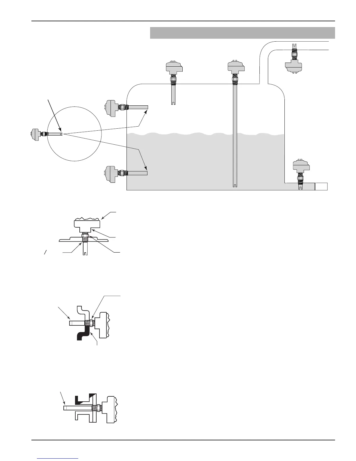
Figure 3
Vertical Mounting
2.4 Mounting
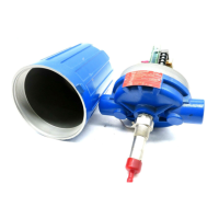
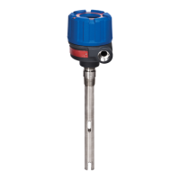
Model 910 level switches are shipped as integral units with
the electronics assembled to the transducer. They may be
mounted in a variety of positions as shown in Figures 2
through 5.
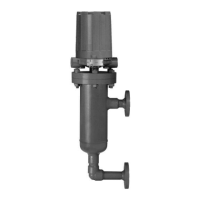
Proper orientation of the transducer gap will provide
maximum performance in difficult applications. When
the switch is mounted horizontally, the transducer gap
must be turned vertical to allow proper drainage of the
liquid media. See Figures 2 and 4.
Screw transducer into the opening using pipe compound
or thread tape. If flanged, bolt unit to mating flange with
proper gasket.
Caution: Never tighten unit on the tank connection by turning the
housing. Use a wrench on the transducer mounting nut
flats. Use thread tape or suitable pipe compound on the
threads. Do not overtighten.
When installed in a nozzle or pipe, the transducer gap
must extend into the tank at least one inch beyond the
inside tank wall. Refer to Figure 5.
 Loading...