EasyManua.ls Logo

Magnetrol Eclipse 706-512 User Manual

Magnetrol Eclipse 706-512
16 pages
To Next Page IconTo Next Page
Page #1 background imageLoading...
Page #1 background image
SIL Certified Safety Manual for
Eclipse
®
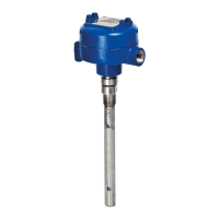
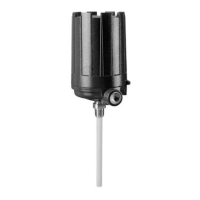
Model 706-512X-XXX
High Performance Guided Wave
Radar Level Transmitter
This manual complements and is intended to be used with the
Magnetrol
®
Eclipse
®
Model 706 High Performance Guided Wave
Radar Installation and Operating manual (Bulletin 57-606).
Safety Function
The HART
®
version of the Eclipse
®
Enhanced Model 706
Guided Wave Radar (GWR) transmitter will measure
level and transmit a signal proportional to that level
within the stated safety accuracy of ±2% of span (or the
measured error published in I/O Manual 57-606,
whichever is greater). In addition, when continuous,
automatic diagnostics detect that the transmitter cannot
perform this function, the output will be driven to the
customer-specified out-of-range signal (i.e., 3.6 mA or
21 mA).
The Enhanced Model 706 is certified for use in low
demand level measurement applications.
Application
The HART
®
version of the ECLIPSE Model 706
Guided Wave Radar level transmitter can be applied in
most process or storage vessels, bridles, and bypass
chambers up to the probe’s rated temperature and pres-
sure. It can be used in liquids, slurries, or solids with a
dielectric constant in the range 1.4–100 to meet the
safety system requirements of IEC 61508 (Edition 2.0,
2010) and IEC 61511-1.
Benefits
Level protection to SIL 3 as certified by exida
Certification per IEC 61508/IEC 61511-1.
Probe designs to +850 °F (+454 °C), 6250 psig
(430 bar) and full vacuum.
Cryogenic applications to -320 °F (-190 °C).
Intrinsically safe, Explosion-proof and Non-Incendive
approvals.
Quick connect/disconnect probe coupling.
Question and Answer IconNeed help?

Do you have a question about the Magnetrol Eclipse 706-512 and is the answer not in the manual?

Magnetrol Eclipse 706-512 Specifications

General IconGeneral
BrandMagnetrol
ModelEclipse 706-512
CategoryTransmitter
LanguageEnglish

Summary

Introduction

Product Description

Details the Eclipse Model 706 high-performance guided wave radar level transmitter and its technology.

Theory of Operation

Explains the Guided Wave Radar (GWR) principle based on Time Domain Reflectometry (TDR).

Determining Safety Integrity Level (SIL)

Outlines the criteria for achieving a Safety Integrity Level (SIL) based on standards.

Applicable Models

Level Measuring System

Miscellaneous Electrical Considerations

Covers electrical aspects like pollution degree and EMC for safety system integration.

Mean Time To Repair (MTTR)

Supplementary Documentation

General Instructions

Systematic Limitations

Details critical limitations to avoid systematic failures in application and environmental conditions.

Installation

Refers to the manual for complete installation instructions and configuration advice.

Skill Level of Personnel

Specifies the required technical expertise for personnel performing manual procedures.

Necessary Tools

Lists the tools required for proper setup, configuration, and maintenance of the transmitter.

Configuration Information

Covers essential configuration parameters, password protection, and best practices.

Site Acceptance Testing

Describes the process for verifying proper operation after installation and configuration.

Recording Results

Emphasizes the need to record site acceptance testing results for future reference.

Maintenance

Discusses maintenance aspects, diagnostics, and troubleshooting for the transmitter.

Recurrent Function Tests

Proof Testing

Provides a suggested proof test procedure to detect dangerous undetected failures in the device.

Safety Requirements

System Safety Assumptions

Lists critical assumptions made regarding the product's usage within a Safety Instrumented Function (SIF).

Safety Function Requirements

Defines the specific safety-relevant functionality and performance requirements for the transmitter.

Safety User Programming and Configuration Requirements

Outlines requirements for field configuration to create and maintain SIF configurations.

Appendices

SIL Certificate

Presents the official exida certificate confirming the device's SIL capability.

FMEDA Report: exida Management Summary

Summarizes the Failure Modes, Effects, and Diagnostic Analysis for the transmitter.

Specific Model 706 Values

Provides specific SIL, HFT, SFF, and PFDavg values for the Model 706.

Report: Lifetime of Critical Components

Discusses the assumed useful lifetime of critical components for long-term reliability.

Related product manuals