Do you have a question about the Magnetrol ES Modulevel and is the answer not in the manual?
Procedures for carefully unpacking the electronic Modulevel displacer level transmitter and its components.
Guidelines to reduce the risk of component failure due to static electricity during handling.
Essential checks and preparation steps before commencing the installation process.
Factors to consider for optimal placement, operation, and protection of the transmitter.
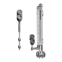
Details on how to mount the Modulevel transmitter using various connection types and configurations.
Specific instructions for installing the Modulevel transmitter in a tank top configuration.
Step-by-step guide for mounting the Modulevel transmitter with a chamber type connection.
Instructions for wiring the Analog EZ Modulevel transmitter when it is integrally mounted.
Wiring procedures for Analog EZ Modulevel transmitters that are mounted remotely.
Guidelines for proper wiring installations in hazardous locations for Analog EZ Modulevel.
Procedures for calibrating the Analog EZ Modulevel transmitter for accurate measurements.
Step-by-step guide for calibrating the transmitter in the field for direct acting applications.
Instructions for field calibration of the transmitter set for reverse acting applications.
Procedure for calibrating the Analog EZ Modulevel on a calibration stand.
Wiring instructions for the Digital ES II Modulevel transmitter in integral mounting configurations.
Wiring procedures for Digital ES II Modulevel transmitters with remote mounting.
Guidance for safe wiring of the Digital ES II Modulevel in hazardous environments.
Calibration methods for the Digital ES II Modulevel using its on-board push-buttons.
Detailed steps for calibrating the Digital ES II Modulevel in the field using push-buttons.
Instructions for calibrating the Digital ES II Modulevel on a bench stand using push-buttons.
Steps to configure the digital meter display and function on the Digital ES II Modulevel.
Procedures for calibrating the transmitter for interface level measurements in various liquids.
How to connect a HART communicator to the Digital ES II Modulevel transmitter.
Overview of the typical display menu structure when using a HART communicator.
Steps for performing basic field calibration using a HART handheld communicator.
Navigating the HART menu structure for configuration and calibration.
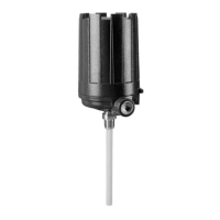
An overview of the Electronic Modulevel Displacer Level Transmitter's design and operation.
Explanation of the buoyancy principles and LVDT technology used in the Modulevel transmitter.
Common problems, symptoms, and corrective actions for the Electronic Modulevel transmitter.
Procedure for replacing the transmitter PC board on the Analog EZ Modulevel.
Instructions for replacing the power supply PC board in 120/240 VAC Analog EZ models.
Steps for removing and installing the LVDT on the Analog EZ Modulevel.
Procedure to verify LVDT winding resistance using a multimeter.
Procedure for replacing the transmitter PC board on the Digital ES II Modulevel.
Steps for removing and installing the LVDT on the Digital ES II Modulevel.
Procedure to verify LVDT winding resistance using a multimeter.
Details on Factory Mutual approvals for various Modulevel models and configurations.
List of CSA certifications and approvals for the Modulevel series.
ATEX approvals and requirements for Modulevel transmitters in explosion-protected applications.
Information on available replacement PC boards for Analog EZ and Digital ES Modulevels.
Component breakdown and part numbers for transmitter head assemblies.
List of recommended spare parts for routine maintenance and common replacements.
Catalog of mechanical components for Modulevel transmitters, including flanges and stems.
Procedures for converting Smart ES or EZ electronics to Digital ES II.
Functional characteristics of the Modulevel transmitter, including measurement principle and output types.
Key performance metrics such as linearity, repeatability, and resolution.
Dimensional specifications and physical characteristics for various Modulevel models.
Part number configuration for steam application Modulevel transmitters up to 600 lbs.
Part number configuration for steam application Modulevel transmitters from 900 to 2500 lbs.
Part number configuration for non-steam application Modulevel transmitters up to 600 lbs.
Guidelines and information required for returning controls for service or replacement.
| Service | Liquid Level Measurement |
|---|---|
| Output Signal | 4-20 mA, HART |
| Housing | Aluminum or Stainless Steel |
| Enclosure Rating | IP66/67, NEMA 4X |
| Type | Transmitter |
| Process Temperature | -40 to 200°C (-40 to 392°F) |
| Material | 316/316L Stainless Steel |
| Accuracy | ±0.5% of span |
| Electrical Connection | 1/2" NPT, M20 |
| Process Connection | Flanged, Threaded |
| Mounting | Top-mounted |