What should I do if my Magnetrol Transmitter shows 'Low Ifc Echo Str'?
- LlruizSep 23, 2025
To address a Low Ifc Echo Str issue with your Magnetrol Transmitter, check the following settings: Dielectric Range and Sensitivity. View the Echo Curve.
What should I do if my Magnetrol Transmitter shows 'Low Ifc Echo Str'?
To address a Low Ifc Echo Str issue with your Magnetrol Transmitter, check the following settings: Dielectric Range and Sensitivity. View the Echo Curve.
What should I do if my Magnetrol Transmitter shows a Ramp Interval Error?
If you are experiencing a Ramp Interval Error with your Magnetrol Transmitter, verify the accuracy of the Level reading. If the issue persists, consider replacing the transmitter electronics. If problems continue, contact MAGNETROL Technical Support.
What to do if Totalizer Data is lost on Magnetrol Eclipse 706 Transmitter?
If the Totalizer Data is lost on your Magnetrol Transmitter, it is recommended to contact MAGNETROL Technical Support for assistance.
How to fix a High Elec Temp error on Magnetrol Eclipse 706?
To resolve a High Elec Temp issue with your Magnetrol Transmitter, shield the transmitter from the heat source or increase air circulation. Alternatively, locate the transmitter remotely in a cooler area.
What does 'Calibration Req’d' mean on my Magnetrol Eclipse 706 Transmitter and how do I fix it?
If your Magnetrol Transmitter displays 'Calibration Req’d', return the transmitter to the factory for recalibration.
How do I troubleshoot a Low Echo Strength on my Magnetrol Eclipse 706 Transmitter?
To address a Low Echo Strength issue with your Magnetrol Transmitter, check the following settings: Dielectric Range and Sensitivity. View the Echo Curve.
How do I troubleshoot a High Flow Alarm on my Magnetrol Eclipse 706 Transmitter?
If your Magnetrol Transmitter is showing a High Flow Alarm, check the settings for Flow Element Reference Distance, Gen Eqn Factors, and Custom Table entries.
What to do if my Magnetrol Eclipse 706 displays 'No Probe Target'?
If your Magnetrol Transmitter is showing a 'No Probe Target' error, check the settings for Probe Model and Sensitivity.
What to do if my Magnetrol Eclipse 706 Transmitter shows 'EoP Above ProbeEnd'?
To fix an 'EoP Above ProbeEnd' error on your Magnetrol Transmitter, check the following settings: Probe Length, Decrease Sensitivity, and Increase Blocking Distance. View the Echo Curve.
How do I resolve a Low Elec Temp error on my Magnetrol Transmitter?
To address a Low Elec Temp issue with your Magnetrol Transmitter, insulate the transmitter or locate it remotely in a cooler area.
Digital communications system for interconnecting field devices, similar to DCS but with differences in wiring and control distribution.
Technology for interoperability, providing extended descriptions for each object and information needed by the host system.
Controls communication on a FOUNDATION fieldbus segment, maintaining the 'Live List' and coordinating timing.
Supports Intrinsic Safety applications with bus-powered devices via barriers or galvanic isolators.
Describes function blocks used in FOUNDATION fieldbus devices to provide control system behavior, including RB, TB, AI, and PID blocks.
General descriptions of parameters common to all function blocks, such as ST_REV, TAG_DESC, STRATEGY, ALERT_KEY, MODE_BLK, BLOCK_ERR.
Describes device characteristics like name, manufacturer, serial number; has no control function.
Lists and explains parameters specific to the Resource Block, including mode, revision, and features.
Parameters for NE-107 to aid in communicating device conditions, such as FD_VER, FD_FAIL_ACTIVE, FD_OFFSPEC_ACTIVE.
Custom blocks containing parameters pertinent to the transmitter itself, used for level, volume, and flow.
Discusses universal parameters and device-specific parameters like UPDATE_EVT, BLOCK_ALM, DEVICE_STATUS.
Details local and host system password protection for configuration changes; default password is 1.
Highlights the advantage of pre-configured devices for the Model 706 FF GWR transmitter.
Refers to the I/O Manual BE 57-606 for detailed device-specific configuration parameters.
Takes transmitter input data by channel number and makes it available to other function blocks.
General descriptions of parameters common to all function blocks, applicable to AI blocks.
Lists conditions that can cause an AI block to display a BLOCK_ERR diagnostic.
Describes the feature allowing Analog Input block Out values to be displayed on the local LCD.
Explains how Analog Input Block Out values can be conditionally displayed on the LCD, including format and examples.
Provides examples of typical AI Block configurations, illustrating probe length, offset, scaling, and L Type.
Explains the Simulate feature in the Analog Input block and the required hardware jumper.
Contains logic for PID control, including filtering, set point limits, and feed-forward support.
Lists parameters for the PID block, such as ACK_OPTION, ALARM_HYS, ALARM_SUM, ALERT_KEY, BAL_TIME.
Integrates one or two variables over time, compares to limits, and generates discrete output signals.
Lists parameters for the Integrator block, such as TOTAL_SP, INTEG_OPTIONS, CLOCK_PER, PRE_TRIP.
Provides range extension and applies nine arithmetic types for compensation or augmentation.
Lists parameters for the Arithmetic block, such as ARITH_TYPE, BAL_TIME, BIAS, GAIN, OUT_HI_LIM.
Selects the first good, maximum, minimum, or average of up to four inputs and propagates signal status.
Lists parameters for the Input Selector block, such as SELECT_TYPE, MIN_GOOD, SELECTED, OP_SELECT.
Approximates an input/output relationship using up to 21 X, Y coordinates for interpolation.
Lists parameters for the Signal Characterizer block, such as CURVE_X, CURVE_Y, SWAP_2, GRANT_DENY.
Outlines the key information required for configuration using the QuickStart menu for Level Only applications.
Details the four push buttons and hierarchical menu structure for navigation and data entry.
Describes the keystrokes for inputting numeric data like probe length or level offset using digit entry.
Explains how to input data using increment/decrement for parameters like Failure Alarm Delay.
Details the method for alphanumeric character entry, such as for tags.
Outlines the three levels of password protection for restricting access to menu structures and configuration values.
Provides a guide to configure the transmitter based on measurement type (Level, Interface, Volume, Flow).
Describes the Home Screen sequence of Measured Values, showing device tag, value, status, and bar graph.
Explains how to access the Main Menu from the Home Screen, showing DEVICE SETUP, DIAGNOSTICS, MEASURED VALUES.
Presents the configuration menu tree for Device Setup, including Quick Start, Identity, Basic Config, etc.
Covers how the measurement engine runs self-tests and reports fault operations via the STATUS INDICATOR parameter.
Explains how to manipulate diagnostic indicators for verifying configuration and connected equipment.
Lists Model 706 diagnostic indicators, priorities, explanations, and recommended remedies.
Describes how to access diagnostic explanations and remedies via the DIAGNOSTICS menu on the LCD.
Assigns proposed values for Quality, Sub-status, and Limit for various diagnostic conditions.
Lists requirements for establishing communication on a FOUNDATION fieldbus segment.
Shows example screens indicating when a block should be set to Out of Service (OOS).
Contains tables listing parameters for Transducer, Volume, and Flow blocks.
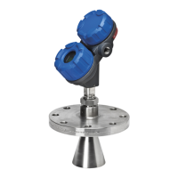
| Model | Eclipse 706 |
|---|---|
| Category | Transmitter |
| Type | Guided Wave Radar |
| Technology | Guided Wave Radar (GWR) |
| Application | Liquid level measurement |
| Output Signal | 4–20 mA with HART, FOUNDATION Fieldbus, or Profibus PA |
| Power Supply | 9-32 V DC (Fieldbus) |
| Process Connection | Flanged |
| Material | 316L stainless steel |
| Enclosure Rating | IP67 |
| Approvals | ATEX, IECEx, FM, CSA, SIL 2/3 |
| Accuracy | ±1 mm or 0.1% of distance to target (whichever is greater) |
