20
BE57-646 ECLIPSE Guided Wave Radar Transmitter - FOUNDATION fieldbus
™
Below are shown some examples of various typical AI Block
configurations.
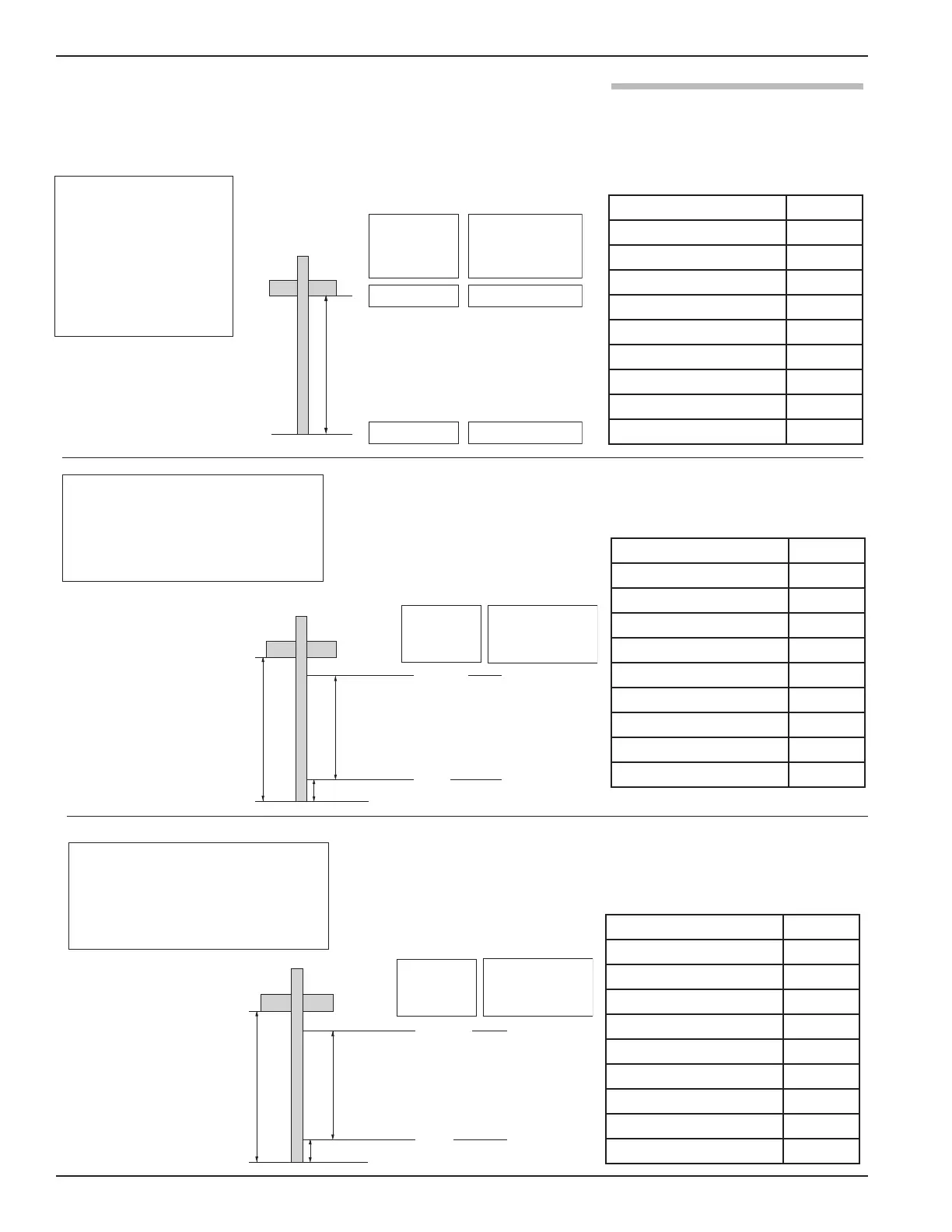
Probe
PL [in / cm]
Probe Length = PL Inches orcm
Transducer
Block +
LCD Level
AI Block Output
[To FF segment]
100%
0[in / cm] 0%
Probe
Probe
Length
111 cm
81.3 cm
0cm
100%
0%
Offset = –15.5 cm
Transducer
Block +
LCD Level
AI Block Output
[To FF segment]
Configuration
Probe Length 111
Level Offset -15.5
XD Scale EU at 0% 0
XD Scale EU at 100% 81.3
XD Scale Units cm
Out Scale EU at 0% 0
Out Scale EU at 100% 100
Out Scale Units %
L Type Indirect
Configuration
Probe Length 111
Level Offset -15.5
XD Scale EU at 0% 0
XD Scale EU at 100% 81.3
XD Scale Units cm
Out Scale EU at 0% 0
Out Scale EU at 100% 81.3
Out Scale Units cm
L Type Direct
Probe
Probe
Length
111 cm
81.3 cm
0cm
81.3 cm
0cm
Offset = –15.5 cm
Transducer
Block +
LCD Level
AI Block Output
[To FF segment]
Configuration
Probe Length PL
Level Offset 0
XD Scale EU at 0% 0
XD Scale EU at 100% PL
XD Scale Units in/cm
Out Scale EU at 0% 0
Out Scale EU at 100% 100
Out Scale Units %
L Type Indirect
Example 1: standard
configuration for trans-
mitter with probe of
length PL inches or cm.
[setup by factory as
part of final assembly
procedure]
Example 2: end user desires 0 to
100% output for a subset of the
measureable region [probe]
[e.g., for a chamber application]
Example 3: same configuration as
previous except Direct [no] scaling
setup in AI block
Output to FF segment is in cm