3.0 Digital ES II Modulevel
Wiring and Calibration.
C
aution: The Digital ES II Modulevel Transmitter operates at
voltages of 12-36 VDC. Incorrect voltages will
damage the transmitter.
All wiring between the power supply and the Modulevel
transmitter should be made using 18-22 AWG shielded
twisted pair instrument cable. All wiring connections to
the transmitter are made in the attached junction box.
NO WIRING CONNECTIONS ARE REQUIRED
INSIDE THE TRANSMITTER HOUSING ON
INTEGRAL UNITS. Instructions for wiring the
Modulevel transmitter depend on type of mounting, inte-
gral or remote, and the area classification required, intrin-
sically safe, explosion proof or non-incendive.
WARNING! Turn off all power before making any electrical
connection.
3.1 Integral Transmitter Wiring
Note: Before connecting the power supply to the transmitter,
be sure that the voltage identification on the name-
plate matches the power supply. Do NOT attempt to
operate this unit at voltages other than as identified as
it will damage the unit.
1. Remove the cover to the junction box of the transmitter.
2. If unit is supplied with meter, access terminal board by
pulling meter straight out until it unplugs. See Figure 16.
If unit has no meter, terminal board is already accessible.
3. Install an approved seal within 18" of the junction box
conduit.
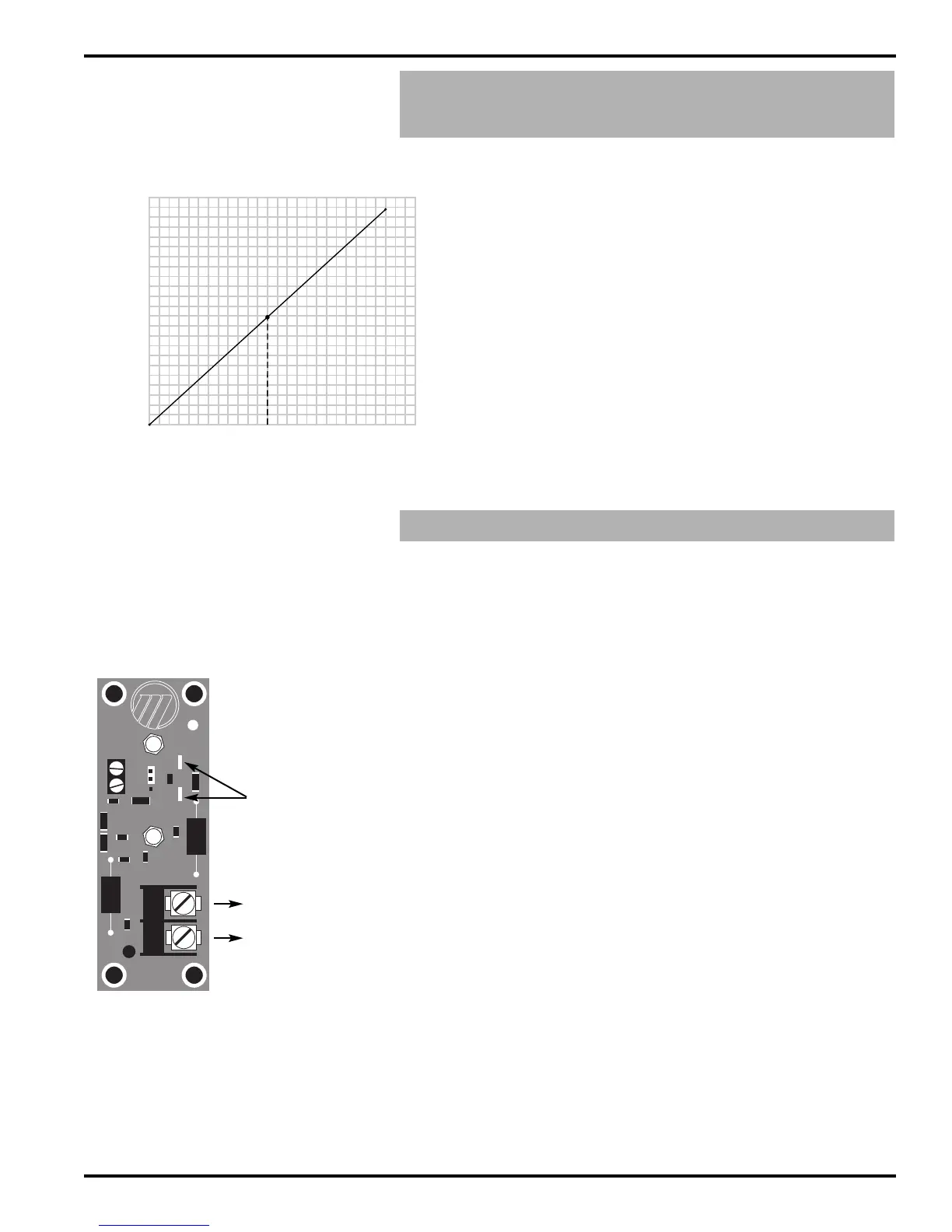
4. Pull the supply wires and connect to the terminals as indi-
cated in the wiring. See Figure 18.
5. Replace meter, if supplied, by pushing banana plugs firmly
into receptacles.
6. Replace junction box cover. Ensure that the cover is tight-
ened down sufficiently to compress o-ring seal.
Note: When operated from a 24 VDC source, the maximum
allowable loop resistance is 545 ohms for Digital ES II
Modulevels. See Figure 17.
When using HART, a loop resistance of 250 to 450 ohms
must be placed in series with the Digital ES II Modulevel.
Caution: Instrument and conduit junction box covers must
in place and tightly sealed at all times during
operation.
TB2
D1
P1
P2
C6 L5
C5
C3
TB1
+
–
+
–
–
+
AW3175
L3
D2
JP1
L6
L4
L2
C1
C4
+
–
Figure 18
Digital ES II Terminal Board
DC+
DC-
}
Signal Power Supply
min 12 VDC
max 36 VDC
14
48-618 ES/EZ Modulevel Displacer Level Transmitter (Top Hat Assembly Design)
Loop Resistance vs. Power Supply Voltage
12 14 16 18 20 22 24 26 28 30 32 34 36 38
0
1
00
200
300
400
500
600
7
00
8
00
9
00
1
100
1000
MAXIMUM LOOP RESISTANCE (Ohms)
(Including Barrier Resistance)
5
45 ohms at 24 VDC
(Digital ES II)
1090 ohms @ 36V
Figure 17
Digital ES II
Maximum Loop Resistance
meter
hook-ups