• Handle circuit boards only by the edges. Do not touch
components or connector pins.
• Ensure that all electrical connections are completely made
and that none are partial or floating. Ground all equipment
to a good, earth ground.
1.3 Before You Begin
1.3.1 Site Preparation
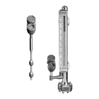
Each Modulevel transmitter is built to match the specific
physical specifications of the required installation. Ensure
that the process connection(s) on the vessel matches the
Modulevel’s process connection(s).
See Mounting, Section 1.4.
Ensure that the wiring between the power supply and
Modulevel transmitter are complete and correct for the
type of installation.
See Specifications, Section 4.8.
When installing the Modulevel transmitter in a general
purpose or hazardous area, local, state and federal regula-
tions and guidelines must be observed.
See Wiring, Sections 2.0 & 3.0.
1.3.2 Equipment and Tools
No special equipment or tools are required to install
the Electronic Modulevel. The following items are
recommended:
• Wrenches, flange gaskets and flange bolting appropriate
for process connection(s)
• Flat-blade screwdriver
• Level
•
1
⁄8" Allen wrench
• Power supply which matches voltage identification on
nameplate
• Multimeter with maximum sensitivity of 100 millivolts for
120 or 240 VAC transmitters
• 250 to 450 ohm resistor for transmitters with HART
communication
2
48-618 ES/EZ Modulevel Displacer Level Transmitter (Top Hat Assembly Design)