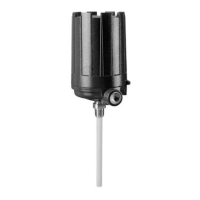
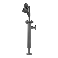
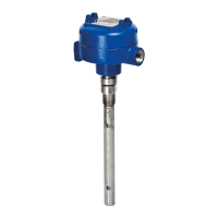
The Kotron Model 805 Smart RF Level Transmitter is a two-wire, 24 VDC, level transmitter that utilizes RF Capacitance for electronic level measurement. This device is designed for trouble-free operation across a wide range of operating conditions and is housed in an ergonomic enclosure with two tandem compartments angled at 45 degrees for ease of wiring and calibration. These compartments are connected via an explosion-proof and watertight feed-through.
Function Description:
The Model 805 measures level by detecting changes in capacitance. A capacitor is formed by two conductive plates (the probe and the tank wall acting as a ground reference) separated by an insulating medium (the dielectric). An AC signal is applied across these plates. As the tank fills with media, the air (dielectric = 1) is displaced by the media, which typically has a higher dielectric constant. This displacement increases the capacitance between the probe and the tank wall, and this change in capacitance is directly proportional to the level of the media. The device provides a 4-20 mA output with an optional HART digital signal, allowing for continuous level measurement. It can be configured for both direct and reverse action.
Important Technical Specifications:
- Measurement Principle: RF Capacitance.
- Measured Variable: Level, determined by change in capacitance values.
- Zero and Range: 0" to 1800" (0 cm to 4572 cm).
- Span: 5 pF min., 10,000 pF max.
- Output:
- Analog: 4 to 20 mA with optional HART digital signal.
- Range: 3.8 to 20.5 mA useable.
- Digital: 0 to 1800" (0 to 4472 cm).
- Resolution: 0.01 mA (analog), 0.1" (digital).
- Loop Resistance (maximum): GP/IS-620 Ω @ 24 VDC.
- Alarm: Adjustable 3.6 mA (no Display or no HART), 22 mA, HOLD.
- Damping: Adjustable 1-45 seconds.
- Power (Measured at instrument terminals):
- General Purpose: 11 to 36 VDC.
- Intrinsically Safe: 11 to 28.6 VDC.
- Process Conditions:
- Maximum process temperature: +1000° F @ 500 psig (+538° C @ 35 bar) (depends on probe selection).
- Maximum process pressure: 5000 psig from -500° to +100° F (345 bar from -296° to +38° C).
- Minimum process pressure: -85° F (-65° C) (depends on probe selection).
- Environment:
- Operating temperature: -40 to +175° F (-40 to +80° C).
- Display function operating temperature: -5 to +160° F (-20 to +70° C).
- Storage temperature: -40 to +175° F (-40 to +80° C).
- Humidity: 0-99%, non-condensing.
- Electromagnetic compatibility: Meets CE Requirements (EN 50081-2, EN 50082-2).
- Housing Material: Aluminum A356T6 (< 0.2% copper).
- Cable Entry: ¾" NPT, M20, PG13.5, PG16.
- Accuracy: ±0.5% of span or 0.1" (whichever is greater) at +20° C (+68° F) reference conditions.
- Repeatability: ±0.1% of span.
- Linearity: ±0.25% of span.
- Hysteresis: ±0.1% of span.
- Response time: < 1 s (adjustable via damping).
- Warm up time: < 5 s.
- Temperature effect: Approximately +0.03%/° C.
Usage Features:
- QuickStart Installation: Provides key steps for mounting, wiring, and configuring, suitable for experienced technicians.
- LCD User Interface: Features a 3-button menu-driven data entry system with a 2-line x 8-character display. The display cycles every 5 seconds to show Level, %Output, and Loop current.
- HART Communication: Compatible with HART Version 5.x, allowing for remote configuration and monitoring using a HART communicator (e.g., HART 275 handheld communicator). This requires a minimum load resistance of 250 Ω.
- Configuration Parameters: Allows users to set units (inches or centimeters), calibrate low and high points (Lo Cal, Hi Cal), set 4 mA and 20 mA points, and adjust damping factor.
- Password Protection: Optional password protection (default is 0) to restrict access to sensitive menu portions, with a numerical value up to 255.
- Probe Types: Supports both rigid and flexible probes, with specific installation instructions for each. Flexible probes require an anchor or weight to keep them taut.
- Mounting Flexibility: Can be mounted to a tank using various process connections (threaded or flanged). The metal tank wall can serve as the reference electrode, or a concentric ground tube (stilling well) can be used for non-conductive vessels or enhanced sensitivity.
- Wiring Options: Supports General Purpose, Non-incendive (Class I, Div 2), and Intrinsically Safe installations. Intrinsically Safe installations require an approved IS barrier in the nonhazardous area. All wiring should use 18–22 AWG shielded twisted pair instrument cable.
Maintenance Features:
- Troubleshooting Guide: The manual includes a comprehensive troubleshooting section with symptoms, potential problems, and solutions for common issues like inaccurate readings, fluctuating values, and error messages (e.g., "805 FAULT (Open/Shorted)", "OSC FAIL", "ABV RNG", "CORRUPT PARAMTRS", "SFWR ERROR", "LEVEL (Uncal)").
- Error Messages: Specific error codes and messages are provided to help diagnose problems, such as open or shorted probes, analog board malfunctions, or configuration parameter loss.
- Diagnostic Tools: The LCD menu includes diagnostic items like "Loop Tst", "Probe Rdg", "Osc Tst", "Opn Prb", and "# Ticks" to assist in fault finding.
- Reinitialization: The "Reinit" function allows resetting all configuration parameters to factory default values, which can be useful for troubleshooting or reconfiguring the device.
- Firmware Version Display: The "Ver n.nAa" menu item shows the firmware version number.
- Replacement Parts: A detailed list of replacement parts is provided, including electronic modules (with or without HART), terminal boards, O-rings, and housing covers.
- ESD Handling Procedures: Emphasizes the importance of observing electrostatic discharge (ESD) safety procedures to prevent damage to electronic components during installation and maintenance.
- Material Build-up: The manual provides information on handling material build-up on the probe, which can affect measurement accuracy.
- Factory Support: In cases where problems persist or passwords are unknown, users are advised to contact the factory for assistance.
- Calibration Data Sheet: A blank data sheet is included for recording configuration and calibration data for future reference.