5
44-604 Top Mounting Liquid Level Switches
2.2 Critical alarm function
It is recommended that for critical alarm functions, an
additional level switch be installed as a high–high or low–
low level alarm for maximum protection.
2.3 Mounting
Caution: Operation of all buoyancy type level devices should be done
in such a way as to minimize the action of dynamic forces
on the float or displacer sensing element. Good practice for
reducing the likelihood of damage to the control is to equal-
ize pressure across the device very slowly.
Ensure that no tubes, rods, or other obstacles in the tank
or vessel which could interfere with the operation of
float(s).
Caution: This instrument is intended for use in Installation Category II,
Pollution Degree 2.
Adjust the process connection as required to bring control
to a vertical position. MAGNETROL controls must be
mounted within three degrees of vertical in all directions.
A three degree slant is noticeable by eye, but installation
should be checked with a spirit level on top and/or sides of
float stem or enclosing tube.
NOTE: Do not insulate switch mechanism housing.
On controls equipped with pneumatic switch assemblies,
consult bulletin on mechanism furnished for air (or gas)
piping instructions.
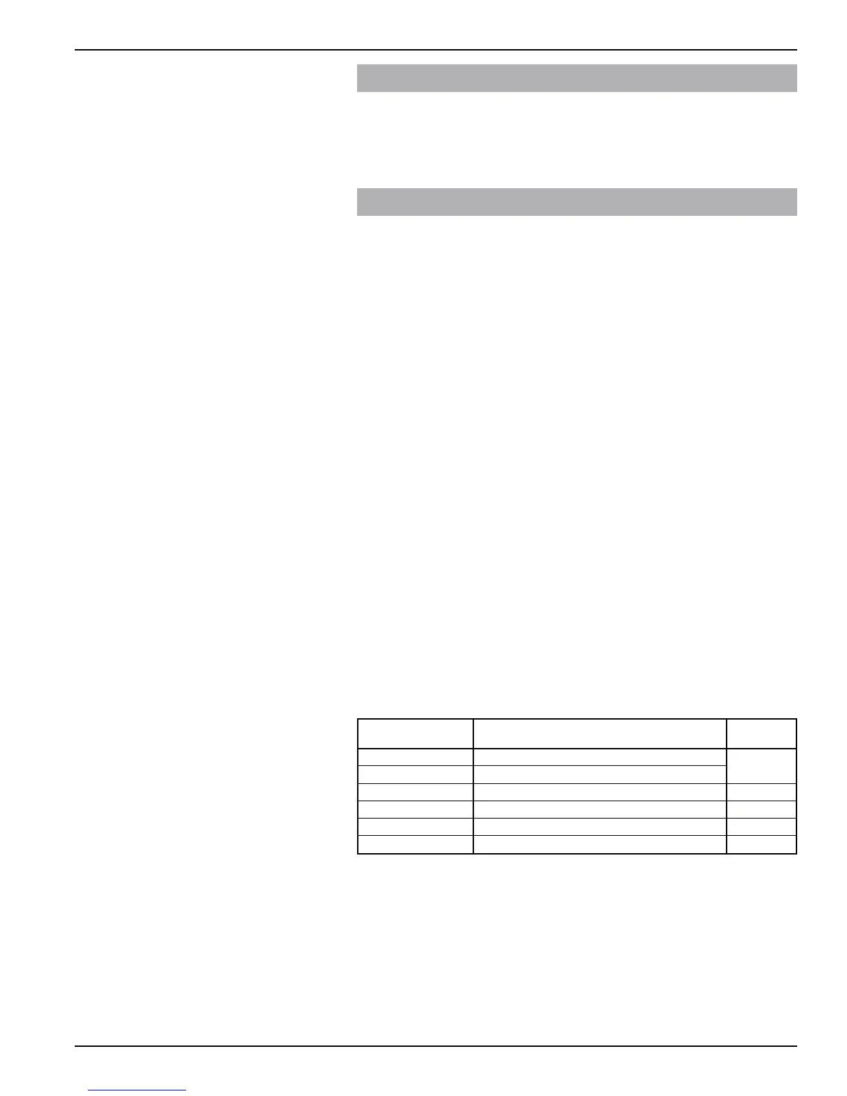
Switch Series Description Bulletin
Letter No.
B, C, D Dry Contact Switch
42-683
F Hermetically Sealed Snap Switch
HS Hermetically Sealed Snap Switch 42-694
J Bleed Type Pneumatic Switch 42-685
K Non-Bleed Type Pneumatic Switch 42-686
R, 8, 9 High Temperature Switch 42-799
 Loading...