Operation Manual MA 25/MA 25e
MA 27/MA 27e
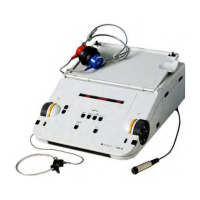
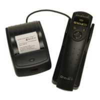
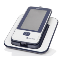
Table 4 Explanation of the Connections
Socket for left headphone jack (blue)
Socket for right headphone jack (red)
Socket for patient response switch
Socket for external power supply unit UES18LCPU-050200SPA
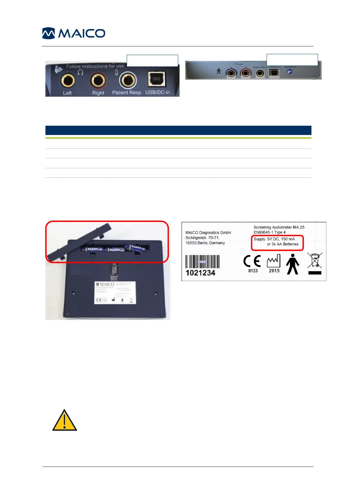
4.2.3 Only for MA 25/MA 25e: Battery Compartment
For battery driven use of the MA 25/MA 25e 3x AA batteries have to be placed in the
battery compartment on the backside of the device (Figure 8 and Figure 9).
4.2.4 Establishing a PC-Connection (MA 25e/MA 27e Only)
To transfer data to a PC, establishing a PC-connection via USB is required. If the
MA25e/MA 27e is used with office equipment that is not a medical device itself (see
Table 4, PC-Connection 1), make sure to establish the PC-connection in one of the
following ways (see Table 5, PC Connection 2, 3 or 4).
Make sure you use only office equipment with the device that
is a medical device itself or meets the requirements of
IEC 60950. If a non-medical device is used within the patient
environment (1.5 m from patient as defined in IEC 60601) a
voltage transformer must be used (exception: a battery driven
laptop is used).
 Loading...