Operation Manual
touchTymp MI 26
and
MI 36
Version
4.2 Hardware Orientation
4.2.1 Display
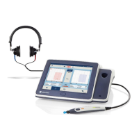
The display on the touchTymp is a touch screen (Figure 15).
This design feature allows use while wearing latex gloves. A
rubber-tipped stylus can also be used to select the desired
function on the screen.
4.2.2 Connections for Accessories, Power Supply and USB-Devices
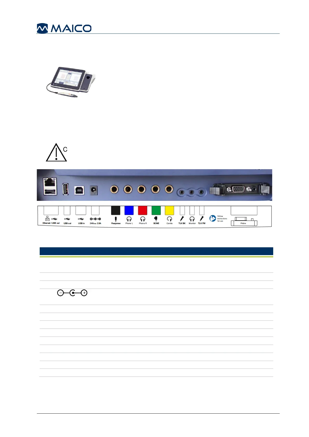
Figure 16 shows the connections on the backside of the device. The connections are
explained in Table 3.
Insert plugs with care into the appropriate connection. Do not
wiggle the plug or pull with force while connected. Disconnect
plugs cautiously. Consider instructions for Changing the Probe
System given in this section.
Figure 16
Table 3 Connections on Backside of Device
Dual connector: Ethernet – no function in actual touchTymp
version / USB A-connection for connection of USB flash drive
USB A-connection for connection of USB flash drive
USB B-connection for data transfer to PC
Power socket for power supply
UES65-240250SPA3
Connection for the Patient Response Switch
Connection for Headphones Left
Connection for Headphones Right
Connection for Bone Conductor
Connection of Contralateral headphone
Connection for Talk Back Microphone
Connection for Monitor Headset
Connection for Talk Forward Microphone
See section 6.3 for more information on the pin assignment.
1 2 3 4 5 6 7 8 9 10 11 12
13
 Loading...