Diode Forward DCA is approx. 0.8mA, Forward voltage drop
open circuit Voltage MAX. 2.2V of Diode
Continuity Test current MAX. 1.5mA Buzzer makes a continuous
sound while resistance is
less than (50Ω)
Function Testing Condition
4.5. Diode & Continuity
Reading
Input Protection: 250V DC or 250V AC RMS
Warning DO NOT apply voltage to Continuity range
5.1. AC Current Measurements
1. Set the Function switch to the 200A/600A range if the approximate range
of the measurement is not known.
2. Set Function switch to 2A/20A for low current readings.
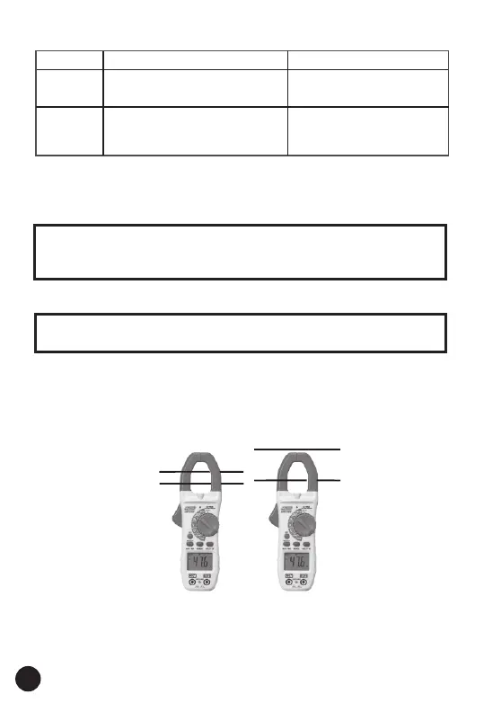
3. Press the trigger to open jaw. Fully enclose only one conductor. For
optimum results, center the conductor in the jaw.
4. The clamp meter LCD will display the reading.
NOTES: Read and understand all Warning and Caution statements in
this manual prior to using this meter. Set the function select switch to
the OFF position when the meter is not in use.
WARNING: Ensure that the test leads are disconnected from the meter
before making current clamp measurements.
5. Operation
CORRECTINCORRECT
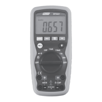
5.2. AC Voltage Measurements
1. Insert the black test lead into the negative COM terminal and the red
test lead into the positive V/Ω terminal.
2. Set the function switch to the V~ position.
8