Do you have a question about the Makita 3612C and is the answer not in the manual?
Ensure a clean, well-lit, dry work area free of hazards like flammable materials.
Wear appropriate clothing, safety glasses, and protective hair covering; avoid loose items.
Do not force tools, use the right tool, secure work, maintain tools, and disconnect before servicing.
Keep children away from the work area and store tools securely out of their reach.
Remove keys, avoid unintentional starting, check damaged parts, and guard against electric shock.
Use heavy-duty, good-condition extension cords suitable for outdoor use when needed.
Use only identical replacement parts and consult authorized service for repairs.
Ensure proper use of polarized plugs and consult an electrician for outlet issues.
Wear hearing protection, handle bits carefully, check for damage, avoid nails, and keep hands away from moving parts.
Hold tool firmly, ensure bit is not contacting workpiece, let tool run briefly, and be aware of rotation direction.
Switch off before removing from workpiece and avoid touching hot bits immediately after use.
Ensure power source voltage matches tool specifications to prevent injury or damage.
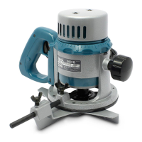
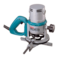
Ensure tool is off and unplugged; insert bit securely using the wrench and correct collet sleeve.
Use the stopper pole and adjusting hex bolt to set desired cut depth, with fine adjustments possible.
Use three adjusting hex bolts for varied depths; loosen nuts, turn bolts, and retighten nuts.
Move the switch lever to ON to start and OFF to stop; ensure shaft lock is released before turning on.
Adjust speed from 9,000 to 23,000 rpm using the speed change knob, with numbers 1-5 indicating speed.
Table shows approximate RPM for each speed setting on the knob.
Ensure tool body rises and chip deflector is installed properly before starting.
Set base on workpiece, turn on, wait for full speed, lower body, and move smoothly.
For edge cutting, workpiece surface should be on the left of the bit in the feed direction.
Adjust feed rate based on bit size, material, and depth; make sample cuts for reference.
Attach to guide holder with wing bolt (B), insert holder, tighten wing bolts (A), and adjust distance with fine adjusting screw.
Move tool with guide flush to workpiece side; use wood for wider guides or thicker pieces.
Attach to guide holder with wing bolt (B), insert holder, tighten wing bolts (A), and adjust distance with fine adjusting screw.
Move tool with guide roller riding the side of the workpiece for trimming and curved cuts.
Loosen screws on tool base, insert templet guide, and tighten screws.
Secure templet to workpiece, place tool on templet, and slide guide along templet side.
Formula provided to calculate distance between router bit and outside of templet guide.
Check and replace brushes when worn to limit mark; replace both at same time using identical parts.
For safety and reliability, have repairs and maintenance done by authorized service centers.
Various templet guides and adapters are available for specific applications.
Includes collet sleeves for different bit sizes and straight/trimmer guides.
Lists specific wrenches and guide holders for tool operation.
Specifications for straight router bits, including carbide tipped and high speed steel options.
Details for hinge mortising bits, available in carbide tipped and high speed steel.
Specifications for veining (single flute) and round nose router bits.
Details for core box and vee grooving bits, including carbide tipped options.
Specifications for 14° dove tail and stagger tooth router bits.
Details for panel pilot and corner rounding bits with ball bearing pilots.
Specifications for beading and cove router bits with ball bearing pilots.
Details for 45° chamfering and rabbeting bits, including solid pilot options.
Specifications for Roman Ogee and self-piloting flush trimmer bits.
Details for self-piloting bevel trimmer and 2 flute flush trimmer bits.
Specifications for combination flush/bevel and 3 flute trimmer assemblies.
Details for 3 flute flush and bevel replacement cutters.
Specifications for 3 flute 22° bevel replacement cutters and 1/4" replacement arbor.
Information on ball bearing pilots with different O.D. and I.D. sizes.
An exploded view illustrating all parts of the Model 3612C electronic router.
The diagram uses numbers to identify individual components for reference.
A detailed list of all parts with their respective item numbers, descriptions, and quantities used.
Lists both main machine components and optional accessories with part numbers.
Details the warranty coverage, period, and conditions for Makita tools.
Outlines conditions not covered by warranty and disclaimers for indirect damages.
| Type | Plunge Router |
|---|---|
| Plunge Capacity | 0-60mm |
| Amperage | 15 A |
| Power Type | Corded |
| Plunge Depth | 0-60mm |
| Power Input | 1850W |
| Weight | 5.5 lbs |
| Net Weight | 5.5 lbs |