Trouble shooting
Fig. D-5
Fig. D-7
Fig. D-6
Test for recognizing the trouble on FET (Field effect transistor) in Controller
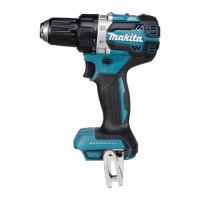
(1) Set Digital tester (1R402) in the diode mode ( mark on the tester: Refer to Fig. D-5.)
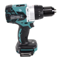
(2) Switch, Terminal, Controller and Stator are connected each other as drawn in Fig. D-6.
Do the following steps.
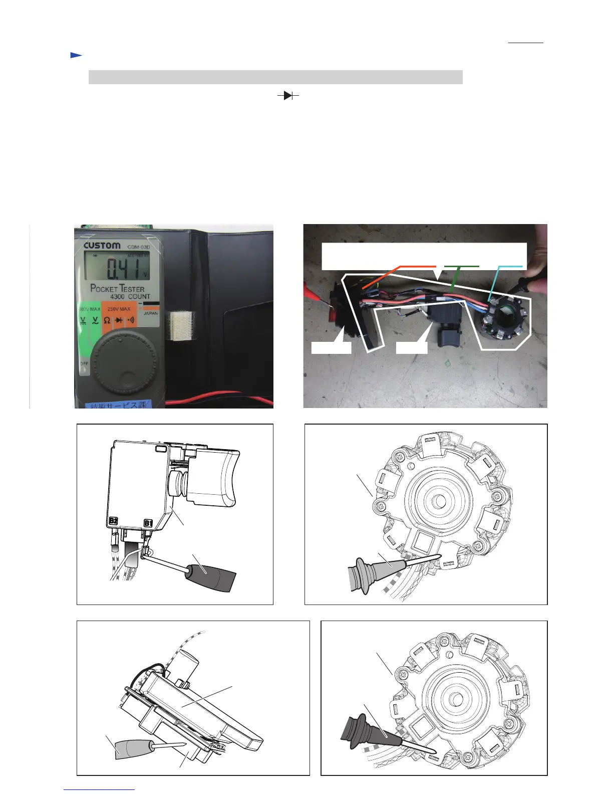
Test 1: Attach Black tester bar to the terminal of white lead wire end on B1 terminal of Switch. (Fig. D-7.)
Attach Red tester bar to one of UVW terminal connected with Red, White, Blue lead wires. (Fig. D-8)
Check the figure in the tester.
Test 2: Attach Red tester bar to minus terminal of Terminal (connected with black lead wire). (Fig. D-9)
Attach Black tester bar to one of UVW terminal connected with Red, White, Blue lead wires. (Fig. D-10)
There is no fault on FET of Controller if the tester indicates within 0.39V - 0.41V in both Test 1 and Test 2.
If either Test 1 or Test 2 results in the improper figure, Controller is broken. Change Stator complete.
Red tester bar
Stator complete
Stator complete
Black tester bar
Switch
Red tester bar
Terminal
Controller (the component
of Stator complete)
Black tester bar
Fig. D-9
Fig. D-8
Fig. D-10
Terminal Switch
Stator complete
(A modular part of Controller, lead wires and Stator)
P 11/ 11
 Loading...