8 ENGLISH
Reversing switch action
►Fig.6: 1. Reversing switch lever
CAUTION: Always check the direction of rota-
tion before operation.
CAUTION: Use the reversing switch only after
the tool comes to a complete stop. Changing the
directionofrotationbeforethetoolstopsmaydam-
age the tool.
CAUTION: When not operating the tool, always
set the reversing switch lever to the neutral
position.
Thistoolhasareversingswitchtochangethedirection
of rotation. Depress the reversing switch lever from the
AsideforclockwiserotationorfromtheBsideforcoun-
terclockwise rotation.
When the reversing switch lever is in the neutral posi-
tion,theswitchtriggercannotbepulled.
Speed change
►Fig.7: 1. Speed change lever
CAUTION: Always set the speed change lever
fully to the correct position. If you operate the
tool with the speed change lever positioned halfway
betweenthe"1"sideand"2"side,thetoolmaybe
damaged.
CAUTION: Do not use the speed change lever
while the tool is running.Thetoolmaybedamaged.
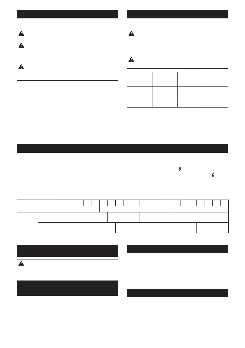
Position of
speed
change lever
Speed Torque Applicable
operation
1 Low High Heavy load-
ing operation
2 High Low Light loading
operation
Tochangethespeed,switchoffthetoolrst.Select
the"2"sideforhighspeedor"1"forlowspeedbuthigh
torque.Besurethatthespeedchangeleverissettothe
correctpositionbeforeoperation.
If the tool speed is coming down extremely during the
operationwith"2",slidethelevertothe"1"andrestart
the operation.
Adjusting the fastening torque
►Fig.8: 1.Adjustingring 2.Graduation 3.Arrow
Thefasteningtorquecanbeadjustedin22stepsbyturningtheadjustingring.Alignthegraduationswiththearrow
onthetoolbody.Youcangettheminimumfasteningtorqueat1andmaximumtorqueat
marking.
Theclutchwillslipatvarioustorquelevelswhensetatthenumber1to21.Theclutchdoesnotworkatthe
marking.
Before actual operation, drive a trial screw into your material or a piece of duplicate material to determine which
torquelevelisrequiredforaparticularapplication.
Thefollowingshowstheroughguideoftherelationshipbetweenthescrewsizeandgraduation.
Graduation 1 2 3 4 5 6 7 8 9 10 11 12 13 14 15 16 17 18 19 20 21
Machine screw M4 M5 M6
Wood
screw
Soft wood
(e.g. pine)
– ɸ3.5 x 22 ɸ4.1x 38 –
Hard wood
(e.g. lauan)
– ɸ3.5 x 22 ɸ4.1x 38 –
ASSEMBLY
CAUTION: Always be sure that the tool is
switched off and the battery cartridge is removed
before carrying out any work on the tool.
Installing or removing driver bit/
drill bit
►Fig.9: 1. Sleeve 2. Close 3. Open
Turnthesleevecounterclockwisetoopenthechuck
jaws.Placethedriverbit/drillbitinthechuckasfar
asitwillgo.Turnthesleeveclockwisetotightenthe
chuck.Toremovethedriverbit/drillbit,turnthesleeve
counterclockwise.
Installing hook
►Fig.10: 1. Groove 2. Hook 3. Screw
Thehookisconvenientfortemporarilyhangingthetool.
Thiscanbeinstalledoneithersideofthetool.Toinstall
the hook, insert it into a groove in the tool housing on
eithersideandthensecureitwithascrew.Toremove,
loosen the screw and then take it out.
Installing driver bit holder
Optional accessory
►Fig.11: 1.Driverbitholder 2.Driverbit
Fitthedriverbitholderintotheprotrusionatthetoolfoot
on either right or left side and secure it with a screw.
Whennotusingthedriverbit,keepitinthedriverbit
holders.Driverbits45mm-longcanbekeptthere.

 Loading...