P 3/ 7
R
epair
[3] DISASSEMBLY/ASSEMBLY
[3]-1. Drill chuck
DISASSEMBLING
DISASSEMBLING
1R223
1R224
Fig. 2 Fig. 3
1R298
1R139
Drill chuck
vise
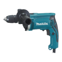
1) Hold 1R298 with Drill chuck.
2) Clamp 1R139 in vise so that flats of Spindle can be fit into 14mm width groove of 1R139.
3) Turn Drill chuck counterclockwise using 1R223, 1R224 and 1R298. (Fig. 2)
Note: If Drill chuck does not work, insert the hook of 781024-2 to a hole of Drill chuck,
then turn Drill chuck counterclockwise. (Fig. 3)
Take the disassembling step in reverse.
Note: Pre-set the fastening torque of 1R223 to 34.3 up to 44.1N.m.
Change lever
(shifted to hammer
drill mode)
1R165
Spindle section
(Spindle, Compression spring 15,
Ball bearing 6002LLB, Retaining ring S-15,
Helical gear 45, Change lever, Steel ball 5.0,
Plate 19, Cam holder complete)
ASSEMBLING
14mm
[3]-2. Carbon brush, Helical gear 45, Ball bearing 6002LLB
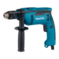
1) Shift Change lever to Drill mode. (Fig. 4) Then separate Housing R from Housing L by removing 4x18 Tapping screws.
Carbon brushes can be removed from Brush holder unit.
2) Shift Change lever to hammer drill mode. Pick up Spindle and Change lever then pivot the Spindle section along
the arc illustrated in Fig. 5.
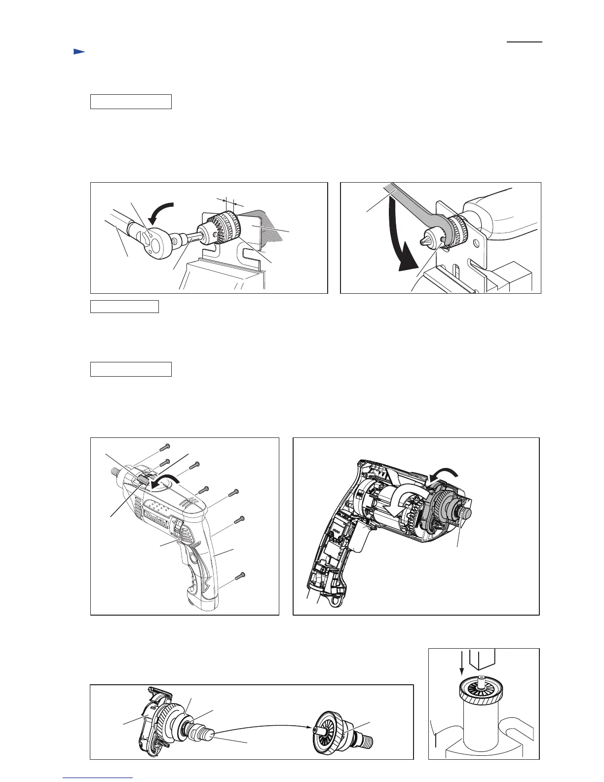
3) Remove Cam holder complete from Spindle section by pulling Spindle. (Fig. 6)
4) Applying 1R165 to Helical gear 45, press Spindle to remove Helical gear 45. (Fig. 7)
5) Remove Retaining ring S-15 with 1R291. Ball bearing 6002LLB and Compression
spring 15 can be removed.
Housing R
Housing L
4x18 Tapping
screw (7pcs.)
Change lever
Drill mode
Hammer drill mode
Fig. 4
Fig. 7
Fig. 5
Fig. 6
Cam
holder
complete
Spindle section except
Cam holder complete
Ball bearing 6002LLB
Spindle
Retaining
ring S-15
Compression spring 15
781014-2
hole of Drill chuck
 Loading...