5
FUNCTIONAL DESCRIPTION
CAUTION:
• Always be sure that the tool is switched off and
unplugged before adjusting or checking function on
the tool.
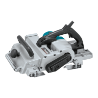
Adjusting depth of cut
1
2
003869
The depth of cut can be adjusted within a range of 0 - 3.5
mm. Turn the knob on the front of the tool until the pointer
is aligned with the desired cutting depth on the scale. Set
the depth of a cut observing the maximum depth which is
limited by width according to the following table.
Width of cut Maximum depth of cut
0 - 150 mm 3.5 mm
150 - 240 mm 2 mm
240 - 312 mm 1.5 mm
Corelation of width of cut and maximun depth of cut
006588
Switch action
1
2
3
003872
CAUTION:
• Before plugging in the tool, always check to see
that the switch trigger actuates properly and returns
to the "OFF" position when released.
For tool with lock button
To start the tool, simply pull the trigger. Release the
trigger to stop. For continous operation, pull the trigger
and then push in the lock button. To stop the tool from the
locked position, pill the trigger fully, then release it.
For tool with lock-off button
To prevent the trigger from being accidentally pulled, a
lock-off button is provided. To start the tool, press the
lock-off button and pull the trigger. Release the trigger to
stop.
Overload protecter (Option)
This tool is equipped with an overload protector which
automatically cuts out to break the circuit whenever
heavy work is prolonged. When it cuts out, inspect the
blade for damage or something wrong. After making sure
that there is nothing wrong with the tool, push the restart
button to resume operation.
Edge fence (Guide rule)
1
2
003873
Edge fence is useful for minimizing a short run of cut by
cutting in a uniform width. The edge fence (guide rule ) is
provided on the side of the tool. Press two pins for the
edge fence (guide rule) so that the edge fence appears.
Move the tool forward while keeping the flat surface of
the edge fence in contact with the side of the workpiece.
To return the edge fence to an original position, push it
upwards from its underside.
Foot
1
23
003874
After a cutting operation, raise the back side of the tool
and a foot comes under the level of the rear base. This
prevents the tool blades to be damaged.
Guideline of cutting blade passage
1
003875
1. Front base
1. Rear base
2. Foot
3. Planer blade
1. Pins
2. Edge fence
(Guide rule)
1. Switch trigger
2. Lock button /
Lock-off button
3. Restart button
1. Knob
2. Scale plate
 Loading...