[3] DISASSEMBLY/ASSEMBLY
[3] -3. Armature and Switch
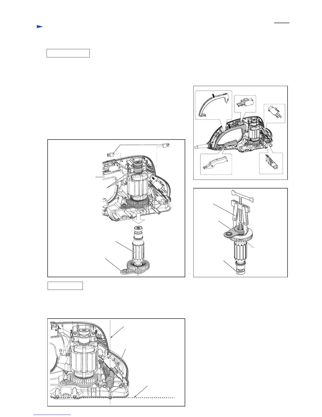
Fig. 15
Fig. 17
Fig. 16
Fig. 18
DISASSEMBLING
ASSEMBLING
(1) Remove Shear blade complete and Helical gear 67. (Refer to pervious pages.)
(2) Switches, Switch lever A / C and Switch arm can be removed. (Fig. 15)
(3) Remove Brush holders, and then separate Armature with Bearing box
complete from Housing L. (Fig. 16)
Note: Carbon brushes can be removed without removing Brush holders.
(4) Remove Bearing box complete from Armature using 1R269. (Fig. 17)
(5) Remove Ball bearings 627ZZ and 6000ZZ from Armature shaft using
1R269. (Fig.17)
Take the disassembling step in reverse.
Note: Align the groove of Switch arm with the vertical line of Housing L
against the bottom line. (Fig. 18)
Bearing box complete
Bearing box
complete
Ball bearing
6000ZZ (under
Armature fan)
Armature
Ball bearing
627ZZ
1R269
Carbon brushes
Brush holders
vertical line of Housing L
the bottom line
of Housing L
Switch lever A
Switch
Switch
Switch lever C
Switch arm
Housing L
The groove of Switch arm
must be at vertical position.
Repair
P 4/ 7
 Loading...