12
13
14
15
Removing and installing vibration damper,
changing front crankshaft seal
61
Installing vibration damper
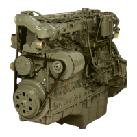
Fig. 12
Place vibration damper on two guide pins (M16 x
1.5). Ensure that the position of the graduated disc
relative to the crankshaft is correct.
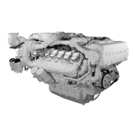
Fig. 13
Tighten mounting bolts (24 mm) to specified
torque.
Note:
Owing to the high tightening torque a rein-
forced socket in conjunction with a 1/2” tool
is required.
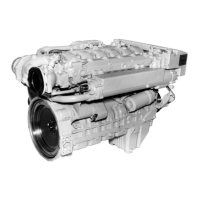
Fig. 14
Screw on delivery start indicator and
V-belt pulleys.
Fit and tension V-belts (see page 118).
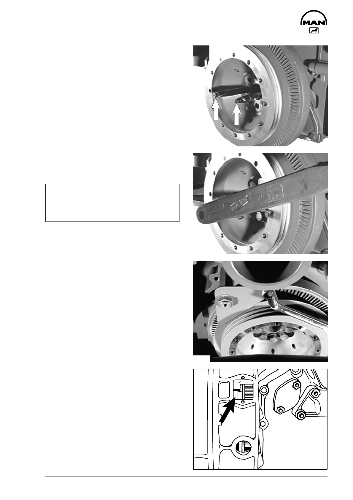
Fig. 15
After the installation, check whether the scale of
degrees on the inspection hole cover of the fly-
wheel housing and on the vibration damper indi-
cate the same values.
If necessary readjust delivery start indicator.
3584
3587
3484
2591
 Loading...