Design and Function
MAN Industrial Diesel Engines D2848/40/42 LE201/203/211/213
27
Carefully read the Operating Instructions before starting any work!
This is especially valid for the chapter on General Safety Instructions
and the safety instructions in each of the chapters.
4 Design and Function
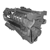
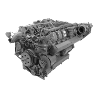
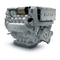
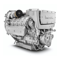
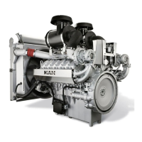
4.1 Engine, General
The 8, 10 and 12-cylinder engines described here are liquid-cooled, 4-cycle diesel engines with turbochar
ging and charge air cooling.
Engine Monitoring
Monitoring of the engine is made through various sensors. The sensors are designed, for example, as rpm
and temperature sensors, which report the various operating conditions of the engine to the engine control
unit. The engine control unit operates according to the EVA principle:
E = Eingang (Input)
V = Verarbeitung (Processing)
A = Ausgang (Output)
The engine control units process the information received from the sensors and control the output signals
which are sent to the actuators. The actuators convert the signals into mechanical factors.
Engine Lubrication
Pressure feed lubrication with one lube-oil pump for the bearings of the crankshaft, connecting rods and
camshafts as well as piston pin sockets, roller tappets and rocker arms.
Oil is filtered through a filter module with an integrated oil cooler and a crankcase breather in the main flow.
Ancillary assemblies such as high-pressure pump, turbocharger and PTOs are connected to the engine oil
circuit.
Cooling System
The cooling circuit is a thermostat controlled forced circulation cooling system. The maintenance-free
coolant pump is mounted to front side on the crankcase and is belt driven. The thermostats are located on
the coolant pump and are made with changeable disks.
Intake and Exhaust System
The dry exhaust pipes are mounted to the cylinder heads. The exhaust is routed to the turbocharger from
the high-pressure stage.
Control of the wastegate valves is made directly by the boost pressure. The engine's main-flow oil circuit
supplies the lubrication for the turbocharger and is connected at the oil pressure connections on the tur
bochargers.
The intake air is routed through the air filter to the turbochargers. The pre-compressed charge air is then
routed to the engine.
Fuel System, General
The fuel system is divided into a low-pressure and a high-pressure system.
The fuel lines, manual pump and the fuel filters are all part of the low-pressure system.
The fuel feed pumps that are flange-mounted to the high-pressure pump act as the interface to the high-
pressure system.
The high-pressure system consist of the high-pressure pump which is fed by the flange-mounted delivery
pumps and the high-pressure lines and injection nozzles.