10 CG-2 | 1.04.00 www.mc-techgroup.com
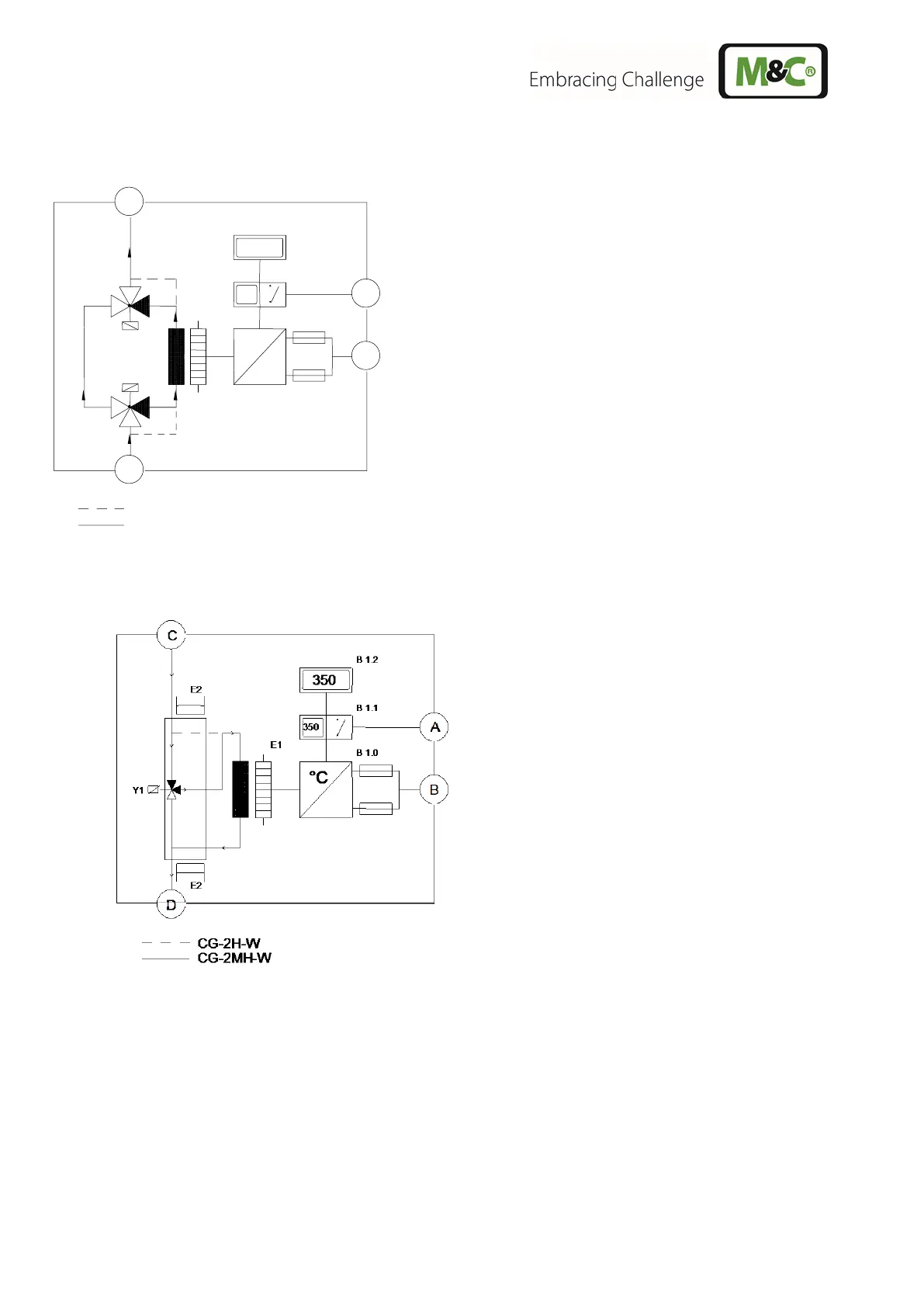
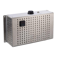
Figures 1 and 2 show the functional scheme of the gas converter type CG..
A Temperature Status Alarm
B Connection for Power Supply
C Sample Gas Inlet
D Sample Gas Outlet
B 1.0 Temperature Controller
B 1.1 Temperature Alarm
B 1.2 Temperature Display
E 1 Tube Furnace
Y 1 3/2-Way-Solenoid-Valve (not with version CG-2)
Y 2 3/2-Way-Solenoid-Valve (not with version CG-2)
Figure 1 Functional diagram of CG-2 and CG-2M
A Temperature Status Alarm
B Connection for Power Supply
C Sample Gas Inlet
D Sample Gas Outlet
B 1.0 Temperature Controller
B 1.1 Temperature Alarm
B 1.2 Temperature Display
E 1 Tube Furnace
E2 Heating bar sample gas inlet and outlet
and Y1
Y 1 3/2-Way-Solenoid-Valve
(not with version CG-2H-W)
Figure 2 Functional diagram CG-2H-W and CG-2MH-W