EasyManua.ls Logo

M&C CG-2 - 10 Description; Figure 4 CG-2 and CG-2 M; Figure 5 CG-2 H-W and CG-2 MH-W

Default Icon
35 pages
Print Icon
To Next Page IconTo Next Page
To Previous Page IconTo Previous Page
Loading...
16 CG-2 | 1.04.00 www.mc-techgroup.com
10 DESCRIPTION
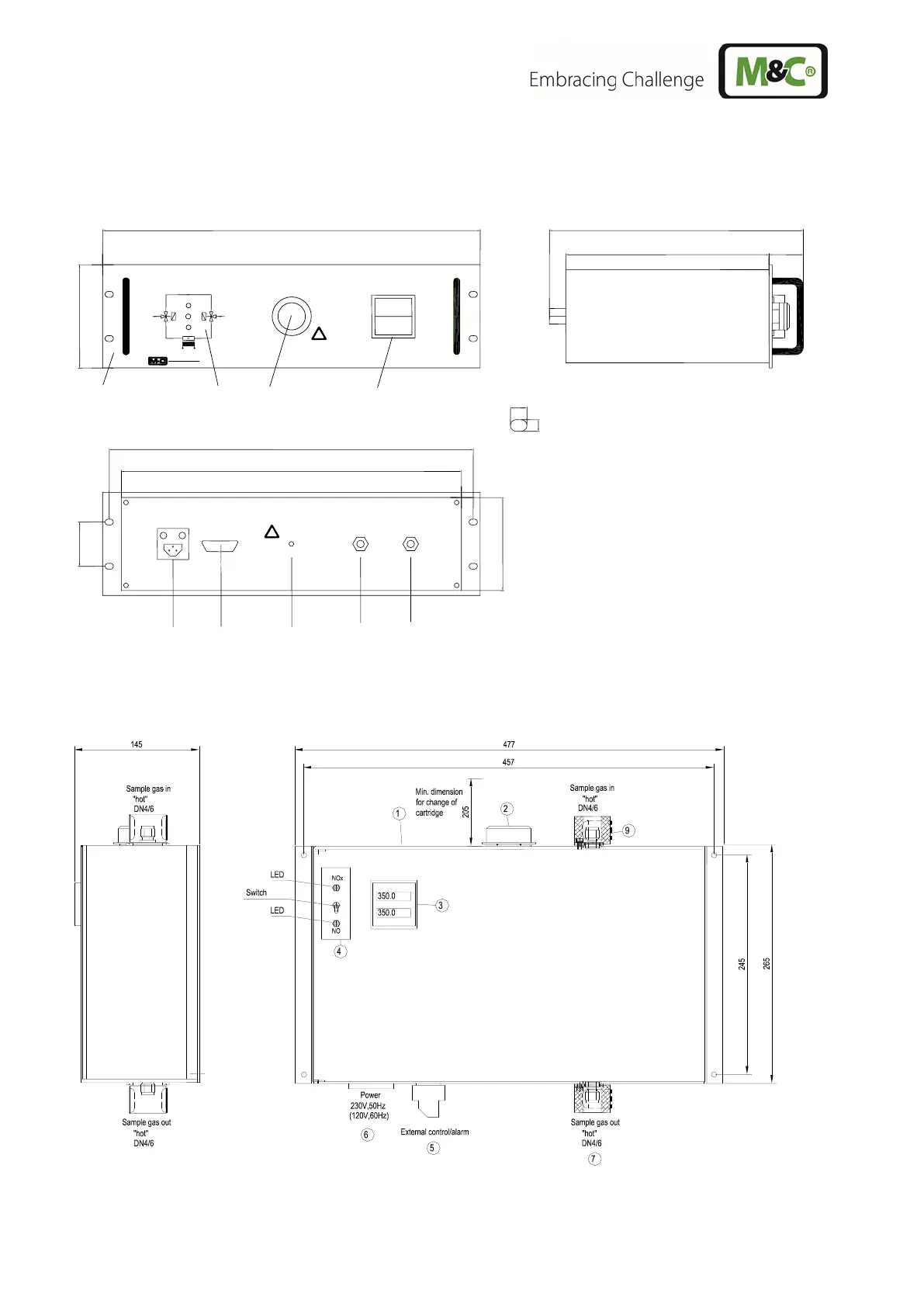
Figure 4 shows the conversion unit version CG-2 and CG-2M in the 19”-rack housing.
Back view
= status alarm temperature sub-D-plug 9 pole
= mains connection, apparatus plug
= sample gas outlet, G1/4i
= sample gas inlet G1/4“ with CG-2/-2M
= sample gas inlet 6mm tube connection*
with CG-2H/-2MH
* Standard
10 (0.39”)
7 (0.28”)
44
(1.73”)
260 (10.24”)
325 (12.8”)
483 (approx. 19”)
435 (17.13”)
465.6 (18.33”)
120
(4.72”)
ø6mm
350
350
G1/4"i
Converter
CG
!
!
57
(2.24”)
132,5
(3HE)
(5.22”)
Figure 4 CG-2 and CG-2M
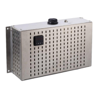
Figure 5 shows the conversion unit versions CG-2H-W and CG-2MH-W in a wall mounting housing.
Figure 5 CG-2H-W and CG-2MH-W
(5.71“)
(18.78“)
(18“)
(9.65“)
(10.43“)
(8.07“)

Table of Contents

Related product manuals