4 CG-2 | 1.04.00 www.mc-techgroup.com
List of Illustrations
Figure 1 Functional diagram of CG-2 and CG-2M .......................................................................... 10
Figure 2 Functional diagram CG-2H-W and CG-2MH-W ................................................................ 10
Figure 3 Notch to differentiate the two cartridge types ................................................................... 12
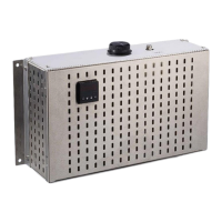
Figure 4 CG-2 and CG-2M ............................................................................................................. 16
Figure 5 CG-2H-W and CG-2MH-W ............................................................................................... 16
Figure 6 Pin configuration in the sub-D-plug X2 ............................................................................. 20
Figure 7 Catalyst life time depending on the NO
2
concentration for varying flow rates and an
Oxygen concentration of 5 vol% ...................................................................................... 23
Figure 8 Catalyst life time depending on the NO
2
concentration for varying flow rates and an
Oxygen concentration of 10 vol% .................................................................................... 23
Figure 9 Catalyst life time depending on the NO
2
concentration for varying flow rates and an
Oxygen concentration of 21 vol% .................................................................................... 23
Figure 10 Adapter for catalyst cartridge with handle ......................................................................... 26
Figure 11 Wiring plan CG-2M, Drawing No.: 2224-5.04.0 ................................................................ 33
Figure 12 Wiring plan CG-2MH-W, Drawing No.: 2224-5.04.4 ......................................................... 34
Figure 13 Wiring plan CG-2H-W, Drawing No.: 2224-5.04.5 ............................................................ 35