18
3
MHT 10120 L M
Series
D
D
7
7
- REPLACE THE POLY-V RIBBED BELT
Replace the ribbed V-belt if one of the following types of damage illu-
strated is present (
C
C
4
4
/
/
3
3)
Take great care while disassembling and assembling the ribbed V-
Take great care while disassembling and assembling the ribbed V-
belt, keeping the fingers well out of the area between the pulley
belt, keeping the fingers well out of the area between the pulley
and the belt.
and the belt.
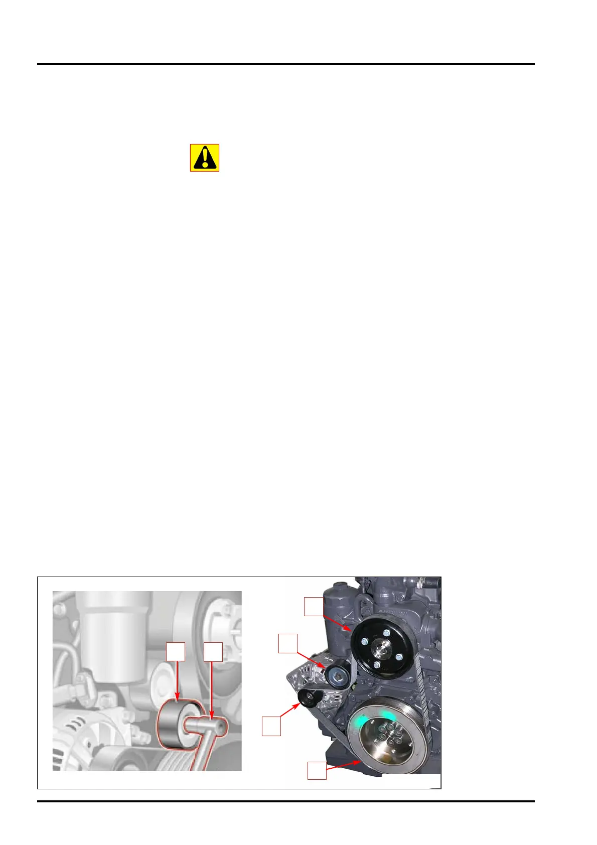
Insert release lever “2” (fig. D7) using a 17 mm wrench on the hex head
screw of the belt tightener roller “1” (Fig. D7) .
Tip the belt-tightener roller upwards and remove the ribbed V-belt.
Reposition the belt-tightener device.
Check to make sure the belt-tightener device and the pulleys are in per-
fect condition (for example, that there are no damaged bearings on the
belt-tightener device, the belt-tightener roller and the return rollers and that
the pulley profile is not worn); replace the components if necessary.
Apply the ribbed V-belt (new) on all the pulleys, except on the belt-tighte-
ner roller (observe Fig. D7 which shows the route of the ribbed V-belt).
Rise the belt-tightener roller by means of a lever, apply the ribbed V-belt
and then bring the belt-tightener roller backwards.
Remove the release lever and check to ensure the ribbed V-belt is lodged
correctly on the pulleys.
Route of the ribbed V-belt (Fig. D7):
3 Alternator
4 Belt-tightener roller
5 Cooling liquid pump
6 Engine shaft
1
2
6
5
4
3
FIG. D7
 Loading...