20
3
MHT 10120 L M
Series
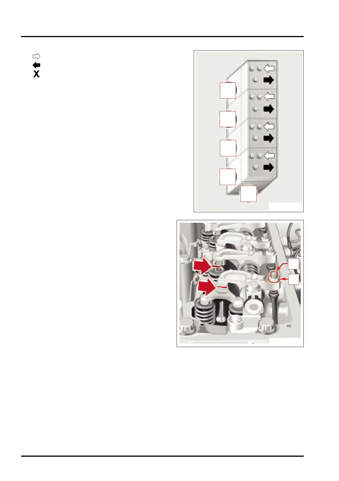
Layout of cylinders and valves (Fig. D8/2)
= suction valve
= discharge valve
= handwheel side
Checking/adjusting the clearance of the valves
Measure the valve clearance between the rocker arm and the
valve stem (discharge valve) or the valves bridge (suction
valve) using a thickness gauge (arrow).
The thickness gauge must be able to pass through with slight
resistance.
Valve clearance:
Valve clearance:
suction valve = 0.40 mm
discharge valve = 0.60 mm
To adjust the valve clearance, slacken lock nut “1” (fig. D8/3).
Adjust the valve clearance by turning adjuster screw “2” (Fig.
D8/3).
Retighten the lock nut. Tightening torque: 18 ft.lb.
Check the valve clearance again and correct it if necessary.
1
2
FIG. D8/2
FIG. D8/3
3
2
1
4
X
 Loading...