SET-UP AND INSTALLATION 777 OPERATOR’S MANUAL
4-72 Published 10-01-12, Control # 044-05
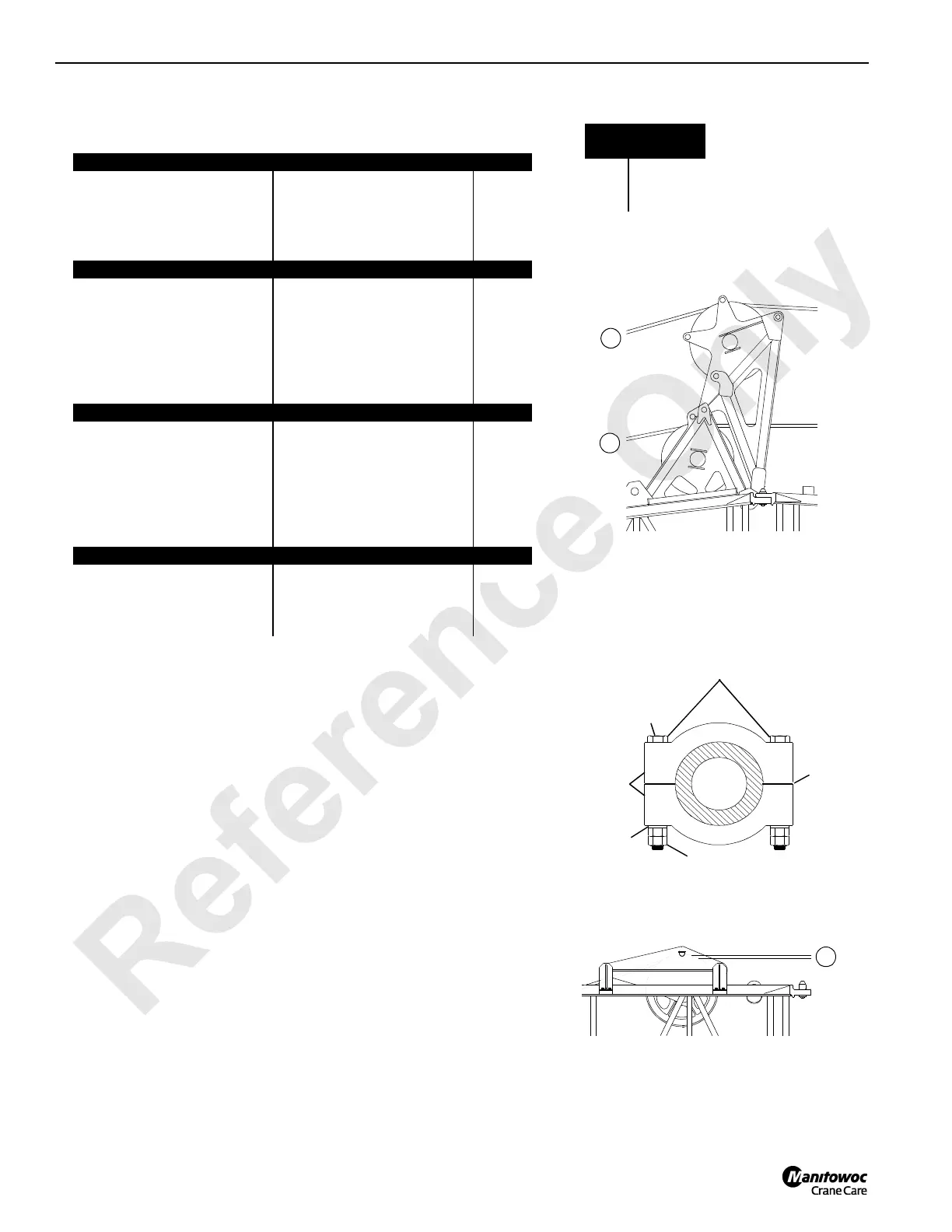
FIGURE 4-47
Notes
1. For this position, sheave bearing must be tight against wire rope guide
frame.
2. Requires optional guide sheave S9 shown in View E.
3. This position is for lead line to upper boom point without load sensing
sheave. If front drum is routed to sheave S5, then sheaves S1 and S2 must
be separated by one set of clamps.
4. This position is for lead line to upper boom point with load sensing sheave. If
front drum is routed to sheave S5, then sheaves S1 and S2 must bear
against each other.
5. Optional sheave S9 must be removed when not in use.
6. Load line from rear drum cannot be routed to fixed jib when optional sheave
(S9) is used.
7. Gap must be equal on both sides of clamps.
Boom Top Guide Sheaves (S1 and S2)
Must Be Positioned at Dimensions Given in This Table
Front Drum to Sheave S1
Lead Line To: Dimension A Note
S3 (View C) 5/8 in (16 mm) 1
S4 (View C) 4-1/16 in (103 mm) —
S5 (View C) 7-23/32 in (196 mm) —
Fixed Jib Point (View E) 11-7/16 in (291 mm) 2
Rear Drum to Sheave S2
Lead Line To: Dimension B Note
S6 (View C) 7-23/32 in (196 mm) —
S7 (View C) 4-1/16 in (103 mm) —
S8 (View C) 5/8 in (16 mm) 1
Upper Boom Point (View F) 10 in (254 mm) 3
Upper Boom Point (View F) 11-7/16 in (291 mm) 4
Fixed Jib Point Not Applicable (see View D) —
Auxiliary Drum to Sheave S2
Lead Line To: Dimension B Note
S6 (View C) 7-23/32 in (196 mm) 4
S7 (View C) 4-1/16 in (103 mm) 5
S8 (View C) 5/8 in (16 mm) 3
Upper Boom Point (View F) 10 in (254 mm) —
Upper Boom Point (View F) 11-7/16 in (291 mm) —
Fixed Jib Point (View E) 11-7/16 in (291 mm) 2
Auxiliary Drum to Sheave S1
Lead Line To: Dimension A Note
S3 (View C) 5/8 in (16 mm) 1
S4 (View C) 4-1/16 in (103 mm) —
S5 (View C) 7-23/32 in (196 mm) —
A1010
Gap between clamps must be equal on
both sides. Torque bolts lubricated with
SAE 20 oil to 120 ft-lb (1 751 Nm)
Clamps
Lockwasher
Note 7
Bolt
Nuts
View A
Boom Butt Guide Sheaves
View B
10 ft (3.1 m) Insert Guide Sheave
A
F
R
Clamp Detail
Load Line
Identification
FFront
RRear
A Auxiliary
 Loading...


