Manitowoc Published 10-01-12, Control # 044-05 4-73
777 OPERATOR’S MANUAL SET-UP AND INSTALLATION
4
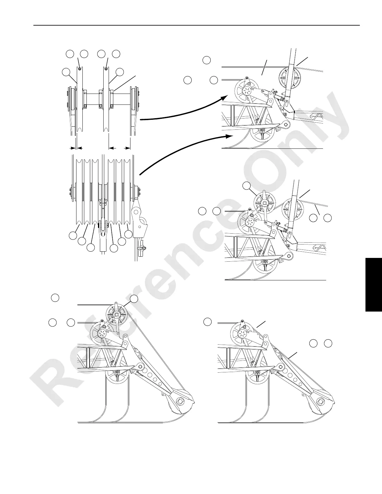
FIGURE 4-47 continued
A1010
Lower
Boom Point
Boom Top
Guide Sheaves
See Clamp
Detail
Fixed Jib
See Note 5
Jib
Strut
View D
Two or Three Load Lines with Fixed Jib
View E
Two Load Lines with Fixed Jib
When Optional Sheave (S9) is Installed
Upper
Boom Point
Lower
Boom Point
Lower Boom Point
Jib
Strut
Fixed Jib
See Note 6
Lower
Boom Point
Lower Boom Point
Upper
Boom Point
View F
Two Load Lines with Upper Boom Point
Lower
Boom Point
Lower Boom Point
Lower Boom
Point
View C
View G
Three Load Lines
with Upper Boom Point
See Note 5
AB
R
F
F
S8
R
A
and
S9
Upper Boom Point
R A
or
or
S9
or
Lower Boom Point
F A
and/or
R A
or
F A
or
S1 S2
S5
S4
S3
S6
S7
F A
AR

 Loading...


