Manitowoc Published 10-01-12, Control # 044-05 v2 3-15
777 OPERATOR’S MANUAL OPERATING CONTROLS AND PROCEDURES
3
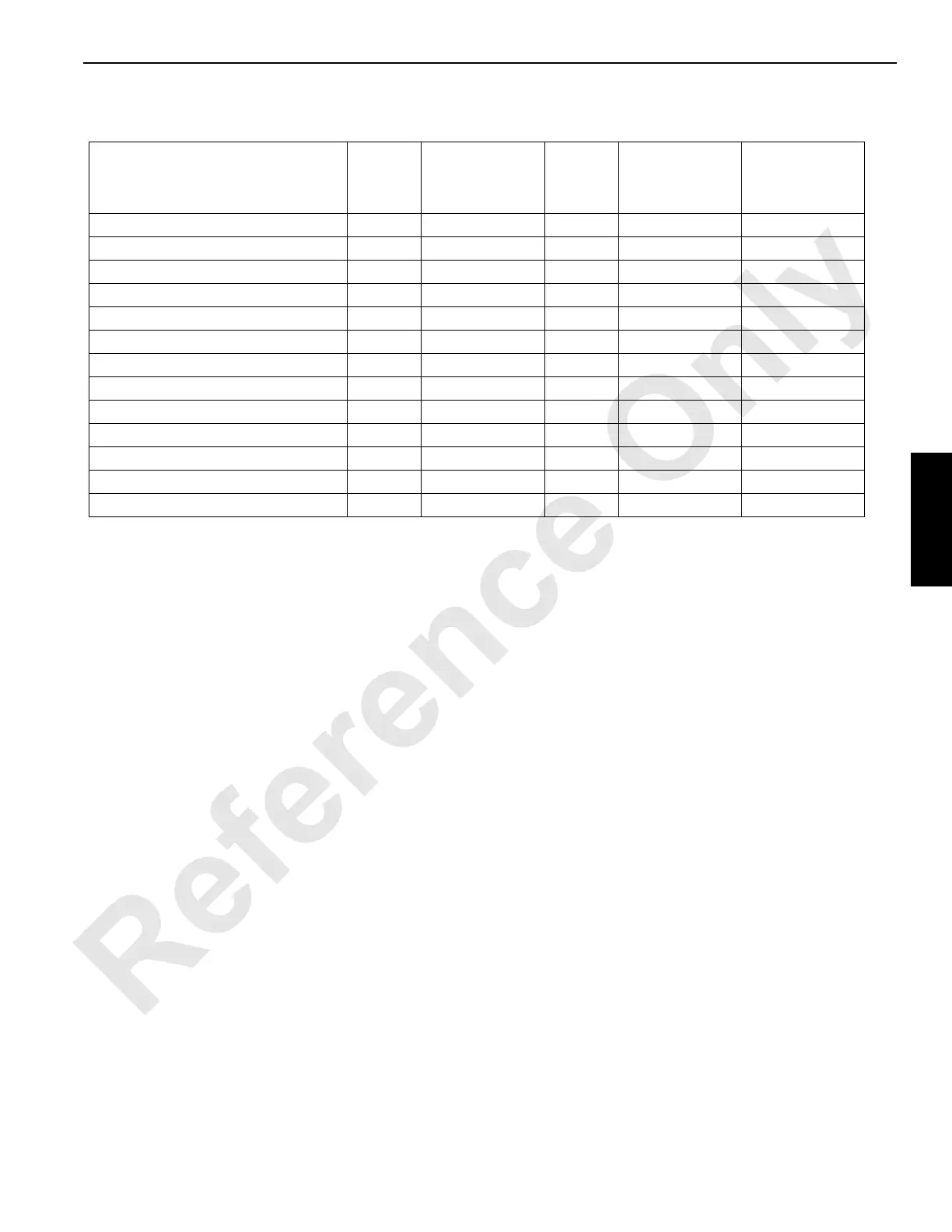
Table 3-2 Bypassable Limit Identification — CRANE S/N 7771165 AND NEWER
Operating Limit
non-CE
1
non-CE
Luffing Jib Setup
Mode On
2
CE
CE
Luffing Jib Setup
Mode On
2
CE
External
Override Switch
Boom Maximum Up No No No No No
Block Up (Drum 1, 2, and 8) Yes Alarm
4
Yes
5
Alarm Alarm
Block Up (Boom Hoist) Yes Alarm Yes
5
Alarm Alarm
Maximum Bail (Drum 1, 2, and 8) Yes No No No No
Minimum Bail (Drum 1, 2, and 8) Yes No No No No
Load Moment (Drum 1, 2, and 8)) Yes Alarm Yes
6,7
Alarm
8
Alarm
Load Moment (Boom Hoist) Yes Alarm Yes
6,7
Alarm
8
Alarm
Pawl In (Drum 1, 2, and 8) Yes No Yes No No
Luffing Jib Max Up 1 Yes Alarm No Alarm Alarm
Luffing Jib Max Up 2 Yes
9,10
Alarm
11
No Alarm
11
Alarm
Luffing Jib Max Down 1 Yes Alarm No Alarm Alarm
Luffing Jib Max Down 2 Yes
10
Alarm No No No
Counterweight Max Up Yes No Yes No No
1
CE = Cranes that comply with 2010 European Requirements.
2
Use only for rigging. See F1. Limit Bypass Switch topic on page 3-16 for instructions.
3
See Rated Capacity Indicator/Limiter Operation Manual.
4
Alarm = Operating limit alarm comes on and fault appears in system fault screen of Digital Display. Operation (motion) of
the corresponding function is not stopped. The alarm is not bypassable.
5
Bypassable if below chart angle, otherwise cutout and alarms active.
6
Bypassed from 100-110% rated capacity with reduced speeds (bypass switch not required).
7
Bypassable when boom or luffing jib is below chart angle for rigging purposes.
8
Only if below chart angle. Otherwise cutout and alarm is active.
9
Bypassable only if boom is below 50 degrees. Otherwise cutout and alarm is active.
10
Bypassable only if handle is returned to neutral while holding bypass switch. Otherwise cutout and alarm is active.
11
Only if boom is below 50 degrees. Otherwise cutout and alarm is active.