OPERATING CONTROLS AND PROCEDURES CD5520/YB5520 OPERATOR MANUAL
3-6 Published 07-06-2017, Control # 406-03
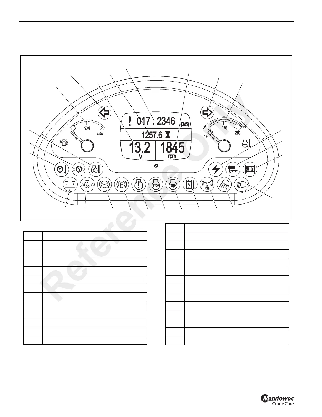
Indicator and Gauge Display
As a system check, the indicators will come on for two seconds when the ignition switch is turned to the RUN position.
(Figure 3-4) Item Numbers
FIGURE 3-4
1
2
3
4
5
6
7
8
9
10
11
12
13
14
15
16
17
18
19
20
21
22
23
24
25
Item Description
1
Fuel Gauge
2 Left Turn Signal
3 Voltmeter
4 Hour Meter
5 Error Code
6 Tachometer
7 Right Turn Signal
8 Coolant Temperature
9 Crane Functions Enabled
10 Outrigger Monitoring Indicator
11
Minimum Wrap Indicator
12 Headlights
Indicator
13 Work Lights
Indicator
14 Axle Lockout Indicator (Not Used)
15 Hydraulic Oil High Temperature
Indicator
16 Engine Wait to Start
Indicator
17 Engine Stop
Indicator
18 Engine Warning
Indicator
19 Parking Brake
Indicator
20 Low Brake Pressure
Indicator
21 Low Engine Oil Pressure
Indicator
22 Low Battery
Indicator
23 Transmission Oil High Temperature
24 Low Transmission Oil Pressure
Indicator
25 Not Used
Item Description
Reference Only
 Loading...


