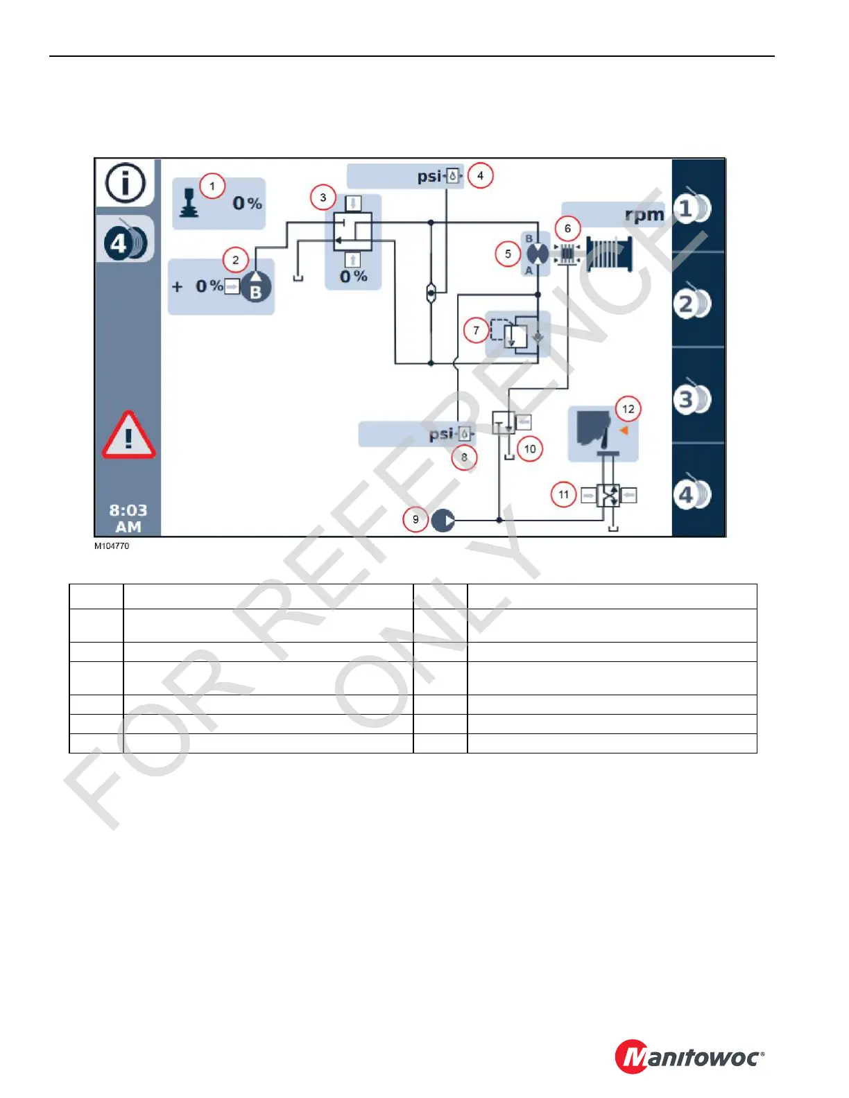
EasyManua.ls Logo

Manitowoc MLC80A-1 - Drum 4 Hydraulic Diagram

Manitowoc MLC80A-1
188 pages
To Next Page IconTo Next Page
To Previous Page IconTo Previous Page
Loading...
HOISTS MLC80A-1/MLC90A-1/MLC100A-1/MLC100-1 SERVICE/MAINTENANCE MANUAL
5-14
Published 10-09-2020, Control # 259-06
Drum 4 Hydraulic Diagram
A detailed hydraulic schematic is provided at the end of Section 2 in this Service Manual.
FIGURE 5-8
Item Drum 4 Components 7 Load Holding Valve
1
Handle (Command -100 to 100%)
+ number = raise, – number = lower
8 Motor Pressure Sensor
2 Pump B (Command 0 to 100%) 9 Accessory Pump
3
Pump B Control Valve (Command -100 to 100%)
+ number = raise, – number = lower
10 Brake Valve
4 System Pressure Sensor 11 Pawl Valve
5 Motor 12 Pawl Cylinder
6 Brake
FOR REFERENCE
ONLY

Table of Contents

Other manuals for Manitowoc MLC80A-1

Related product manuals