Manitowoc Published 10-09-2020, Control # 259-06 2-1
MLC80A-1/MLC90A-1/MLC100A-1/MLC100-1 SERVICE/MAINTENANCE MANUAL HYDRAULIC SYSTEM
SECTION 2
HYDRAULIC SYSTEM
HYDRAULIC SCHEMATIC
The hydraulic schematic for this crane is located at the end
of this section.
HYDRAULIC SYSTEM OVERVIEW
This section provides a physical description and general
functional overview of the major hydraulic components.
Detailed descriptions of the controls and operations using
these components to form working circuits can be found in
the appropriate sections of this manual.
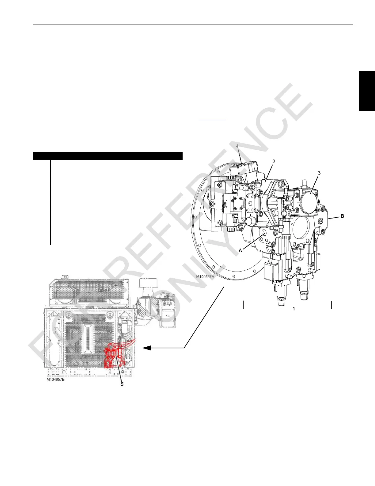
Hydraulic Pump Locations
There are five hydraulic pumps driven by the engine.
Figure 2-1
illustrates the location of these pumps and the
circuits they supply.
.
Pump Supplies Oil To
1Main Pumps:
Side A = High Pressure Accessories (gantry and crawler
cylinders), Drum 2 Primary, Left Crawler, Drum 1
Secondary, and Drum 3
Side B = Right Crawler, Drum 2 Secondary, Drum 1
Primary, sand Drum 4
2Swing
3Fan
4 Low Pressure Accessories: Counterweight Pins, Boom
Hoist Brake and Pawl, Travel Brake and 2-Speed, Drum
1, 2, 3 Brakes
5 Free Fall Drum 1 and 2 (engine mounted if equipped)
FIGURE 2-1