Part Number 020002365 08/25/2015 33
Section 3 Operation
Sequence of Operation
ELECTRONIC CONTROL
Prerequisites
• Potable water must be connected to the carbonator
pump circuit.
• The ice bank water bath water must cover the
evaporator. The compressor will not start unless the ice
bank control probes are immersed in water.
• CO
2
must be supplied.
Initial Power-up
The control has a 30-second delay when power is
connected, or disconnected and reconnected. The display
will show Pd30 - power delay and 30 seconds left in the
countdown cycle.
Normal Operation
NOTE: This sequence of operation includes systems with up
to two recirculation/carbonation circuits. Your model may
not employ a second circuit or second carbonation pump.
Pressing the COMP/AGIT button will start the water
bath agitator immediately and initiate the 180 second
compressor delay. The display will show Cd99 (compressor
delay & 99 seconds) and will start to count down from 99
seconds after the first 81 seconds have elapsed. After 180
seconds the compressor and condenser fan motor energize
and the COMP/AGIT LED flashes. Pressing the CARB A and
CARB B buttons will power the carbonator tank liquid level
control. The corresponding LED flashes to indicate the
pump is running. Pressing the CIRC A & CIRC B buttons will
immediately energize the circulating pumps and energize
the LED constantly. The display will show the circulating
temperature and show the A circuit. When two circuits are
used, the readout will alternate between A and B circuits
every 5 seconds.
The compressor and condenser fan will continue to run
until ice contacts the ice bank control probe closest to the
evaporator. When ice contacts the probe, the COMP/AGIT
LED lights constantly and the compressor and condenser
fan motor de-energize.
As the ice bank melts, the ice bank control probe will lose
contact with the ice; the LED will flash and the compressor
and condenser fan motor will restart. This cycle will repeat
as required depending on load.
Power Interruption
During a power interruption the control will resume from
the point of interruption when power is reapplied and the
time delay expires. Any switches/components that were
energized when power was interrupted will be energized
when power is reapplied.
Error Codes
E1 = Low Water Supply Pressure
E2 = Low CO
2
Pressure
E3 = Low Water Level - Water Bath
E4 = High Water Bath Temperature
E5 = High Water Supply Pressure
E6 = High Refrigeration Temperature
E7 = High Ice Bank Size (Probe Sensor 2)
E8 = Long Carb A Run Time
E9 = Long Carb B Run Time
NOTE: Shorted Transducer = “----”
Open Transducer = “====”
Error codes will display until corrected.
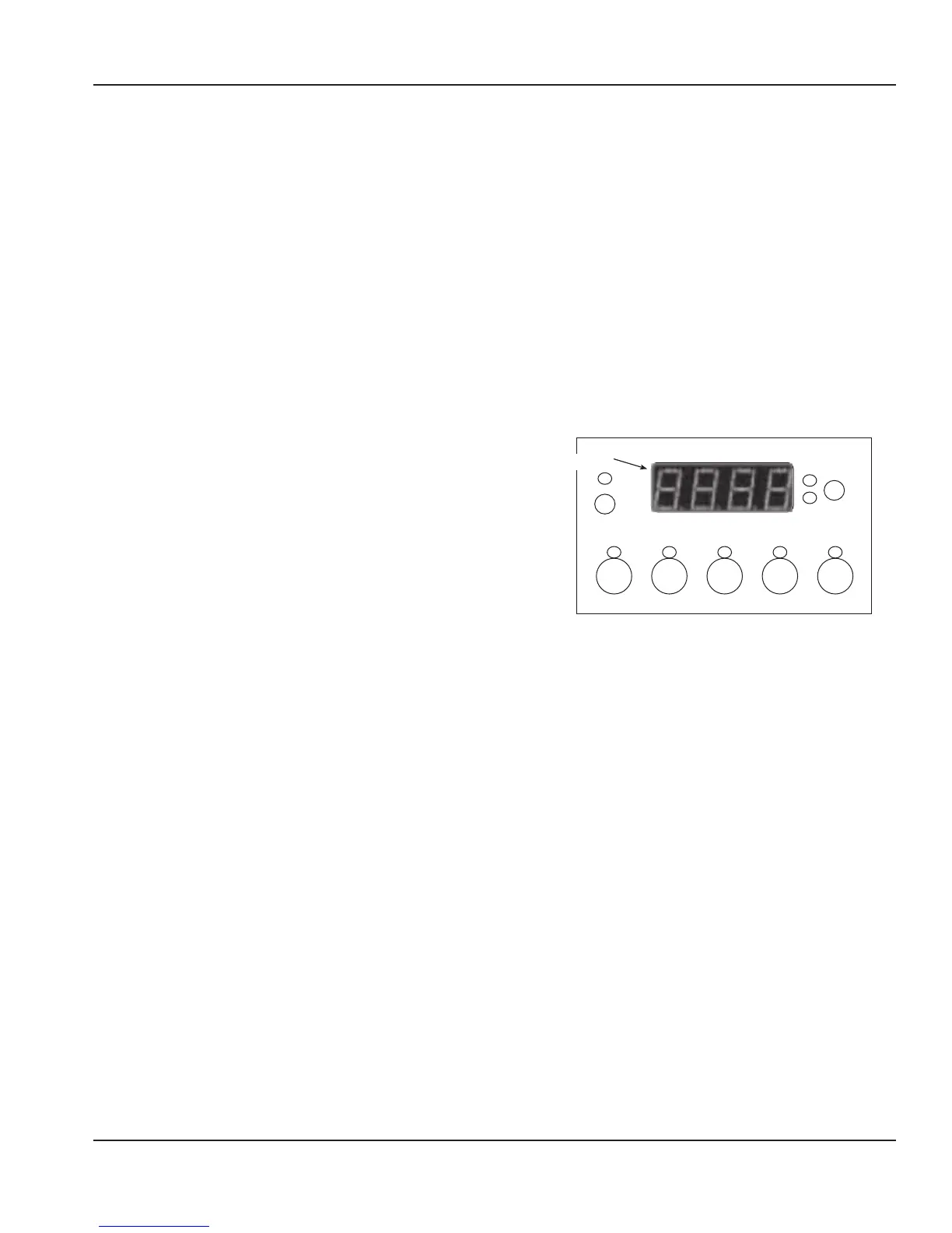
SER
PGM
CIRC
B
CIRC
A
COMP/
AGIT
CARB
A
CARB
B
CIRC
A
CIRC
B
LED Display
Control Programming
There are 5 programming modes:
1. Used to check probes, water bath level, set unit of
measure, & check temperatures.
2. Add additional (third or fourth) circulation pumps
3. For Beermaster Units only - Sets water/glycol
temperature.
4. Temporarily cancel display of error codes.
5. Energy Saving Mode. (G Series Models)
SER Switch
• For when optional LON communication network is
connected.
PGM Switch
• Used to enter and exit programming modes. To enter,
press and hold switch for 3 seconds, repeat to exit.
ū Press and hold Carb B switch — Display will
indicate CO
2
Pressure
 Loading...