4-12 3-29-2018 Control # 610-00
OPERATING CONTROLS - CRANE NBT40-1 SERIES OPERATOR MANUAL
Windshield Wiper Switch
Windshield wiper switch (24, Figure 4-3) is located in
overhead console. This is Hi - Lo toggle type switch with 6
intermittent positions, (intermittent timing is 2-15 seconds,
wiper washer timing is 3 seconds).
Cab Climate Controls
Cab climate controls (25, 26, 27, Figure 4-3) are used to
adjust heating and air conditioning for operator comfort.
360°Swinglock Pedal (if equipped)
Swinglock pedal (28) is located on left side of control cab
floor. Apply pedal to lock turret, release pedal to unlock
turret.
Boom Lift Control Lever
Boom lift control lever (29, Figure 4-4) is located on right
armrest and is used to raise and lower boom. Push lever
forward to lower boom and pull back to raise boom.
Hoist Control Lever
Hoist control lever (30, Figure 4-4) is located on right
armrest. Positioning lever forward lets out hoist rope to lower
load and pulling lever back will raise load.
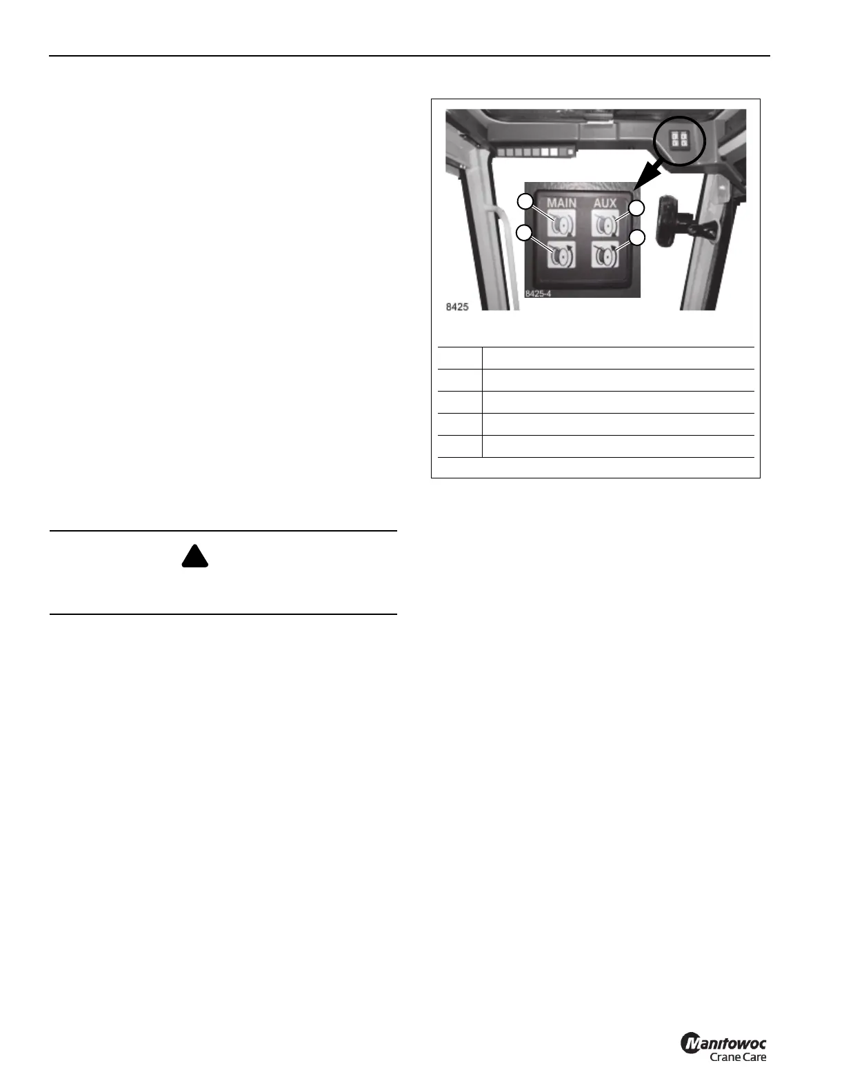
Hoist Rotation Indicator Display
Display is located in front overhead panel Figure 4-7. LED
display illuminates to indicate current hoist in operation and
which direction hoist is rotating.
Hoist Rotation Indicator
Hoist rotation indicator (RDI) is located on top of hoist control
lever (30, Figure 4-3). Indicator is electronically driven by a
signal from an electronic transmitter and sensor attached to
hoist. A pulsating signal is sensed by operator’s thumb
during hoist operation.
Telescope Control Lever
When equipped without auxiliary hoist telescope boom
control lever (31, Figure 4-4) is on left armrest. Push lever
forward to extend boom and pull back to retract boom.
Auxiliary Hoist (Optional)
If equipped with an auxiliary hoist control lever (31,
Figure 4-4) is on left armrest. Positioning lever forward lets
out hoist rope to lower load and pulling lever back reels the
rope in raising load.
Warning Horn Button
Warning horn button (32, Figure 4-4) is located on swing joy
stick. Push switch to sound horn to warn personnel of
pending movement of equipment.
DANGER
Payout loadline before extending boom. Failure to do so
may cause loadline to break or damage equipment.
FIGURE 4-7
8425-6
Item Description
1 Main Hoist UP (Clockwise)
2 Main Hoist DOWN (Counterclockwise)
3 Auxiliary Hoist UP (Clockwise)
4 Auxiliary Hoist DOWN (Counterclockwise)
1
2
3
4

 Loading...


