National Crane 3-29-2018 Control # 610-00 4-13
NBT40-1 SERIES OPERATOR MANUAL OPERATING CONTROLS - CRANE
Swing Control Lever
Swing control lever (33, Figure 4-4) is located on left armrest
and controls turret rotation. Push lever forward to rotate
turret clockwise and pull back to rotate turret
counterclockwise.
Swing control lever can be used to slow and stop swing by
moving control lever to opposite direction of swing. For
example, if lever is pushed forward for a clockwise swing,
pull lever back to slow and stop swing.
Seat Back Adjustment
To adjust back of seat press the seat back adjustment lever
(34, Figure 4-4) located on lower left section of seat back
and then adjust seat as needed.
Seat & Seat Frame Lever
Moving seat slide lever (35, Figure 4-4) will slide seat either
forward or backward, moving seat frame lever (36) slides
seat and seat frame at same time.
Climate Control Unit
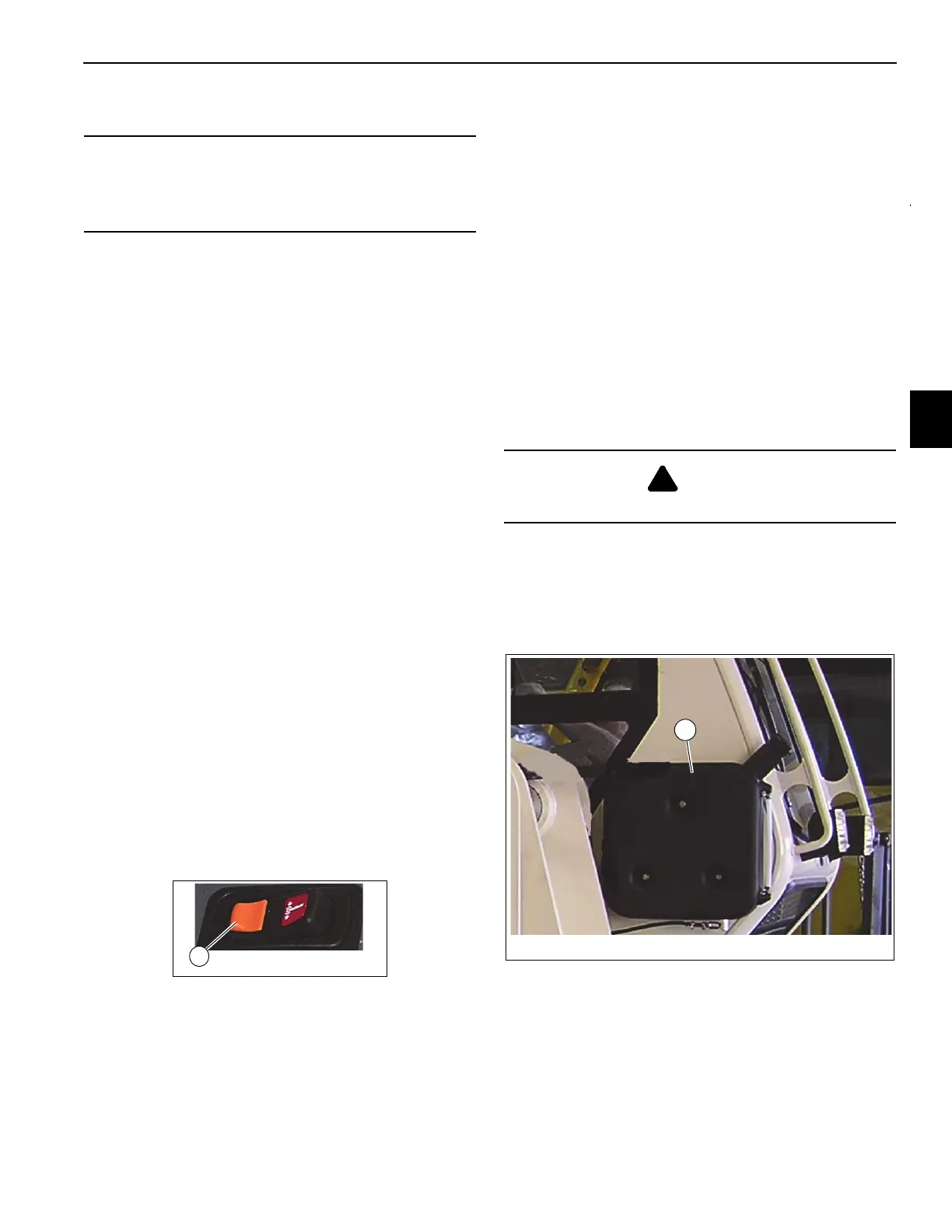
Air Conditioner and Heating of equipment cab is provided by
climate control unit (37, Figure 4-4) located under cab seat.
Swing Brake Switch
Swing brake switch (39, Figure 4-4) is located on left hand
armrest and is used to activate swing brake and park turret in
position. Press switch to activate swing brake to keep turret
from rotating. LED indicator illuminates when switch is
activated. Back half of the switch (1, Figure 4-8) is designed
with a locking mechanism to secure swing brake in locked
position and prevent accidental movement of cab &
superstructure.
House Lock
House lock control (40, Figure 3-3) is a manually operated
mechanical lock that when engaged prevents rotation of
crane superstructure.
To engage lock center boom over front of the cab turn T-
handle clockwise and push knob back into locked position
and move superstructure left to right to align lock pin with the
lock pin hole. To disengage, pull out on T- handle and turn
counter clockwise to lock T- handle and pin in position.
Heater
Diesel powered supplemental heater is stowed under cab
support frame and supplies heat to crane cab (36,
Figure 4-4). Heater controls temperature of crane cab by
cycling coolant between heater and climate control unit
located under cab seat. Controls (25, 26, 27, Figure 4-3) for
heater are located on overhead control panel in crane cab.
Heater Cold Weather Fuel Mixture
At temperatures below -7° C (20° F), add a cold weather
additive or mix kerosene with diesel fuel at a 50/50 ratio, Add
mixture to heater diesel fuel tank (1, Figure 4-9) located on
outside of cab.
Heater Coolant
Heater coolant bottle (1, Figure 4-10) is mounted to turret
and located inside a/c compressor enclosure (2). Coolant
should contain at a minimum a mixture of water and enough
antifreeze to prevent freezing or slushing.
CAUTION
Do not actuate Swing Control Lever while Swing Brake is
engaged, as turret may push through brake. Damage to
swing brake can occur.
WARNING
Do not mix gasoline with diesel fuel.

 Loading...


