6
ASSEMBLY (continued)
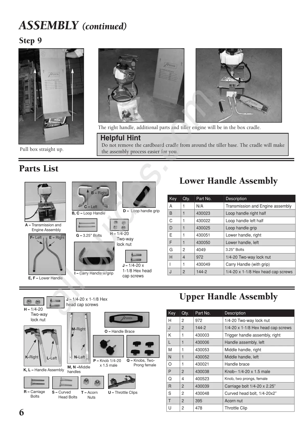
Step 9
Pull box straight up.
The right handle, additional parts and tiller engine will be in the box cradle.
Do not remove the cardboard cradle from around the tiller base. The cradle will make
the assembly process easier for you.
Helpful Hint
Parts List
Lower Handle Assembly
Upper Handle Assembly
Key Qty. Part No. Description
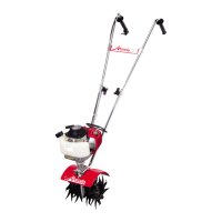
A 1 N/A Transmission and Engine assembly
B
1 430023 Loop handle right half
C 1 430022 Loop handle left half
D 1 430025 Loop handle grip
E 1 430051 Lower handle, right
F 1 430050 Lower handle, left
G2 4049
3.25” Bolts
H 4 972 1/4-20 Two-way lock nut
I 1 430049 Carry Handle (with grip)
J 2 144-2 1/4-20 x 1-1/8 Hex head cap screws
E
K
J – 1/4-20 x
1-1/8 Hex head
cap screws
H – 1/4-20
Two-way
lock nut
B, C – Loop Handle
G – 3.25” Bolts
D – Loop handle grip
I – Carry Handle w/grip
E, F – Lower Handle
A – Transmission and
Engine Assembly
E – Right
B – Right
F– Left
C – Left
Key Qty. Part No. Description
H 2 972 1/4-20 Two-way lock nut
J
2 144-2 1/4-20 x 1-1/8 Hex head cap screws
K 1 430003 Trigger handle assembly, right
L 1 430006 Handle assembly, left
M 1 430053 Middle handle, right
N 1 430052 Middle handle, left
O 1 430021 Handle brace
P 2 430038 Knob– 1/4-20 x 1.5 male
Q4 400523
Knob, two prongs, female
R 2 430039 Carriage bolt 1/4-20 x 2.25”
S 2 430048 Curved head bolt, 1/4-20x2”
T 2 395 Acorn nut
U 2 478 Throttle Clip
K
J –
1/4-20 x 1-1/8 Hex
head cap screws
H – 1/4-20
Two-way
lock nut
S – Curved
Head Bolts
T – Acorn
Nuts
U – Throttle Clips
R – Carriage
Bolts
Q – Knobs, Two-
Prong female
O – Handle Brace
M, N –Middle
handles
P – Knob 1/4-20
x 1.5 male
K, L – Handle Assembly
K-Right
L-Left
M-Right
N-Left
401775 Deluxe 2C Tiller-Cult Manual_Tiller Manual 8/8/11 8:06 AM Page 6
All manuals and user guides at all-guides.com
all-guides.com
 Loading...