7
ASSEMBLY (continued)
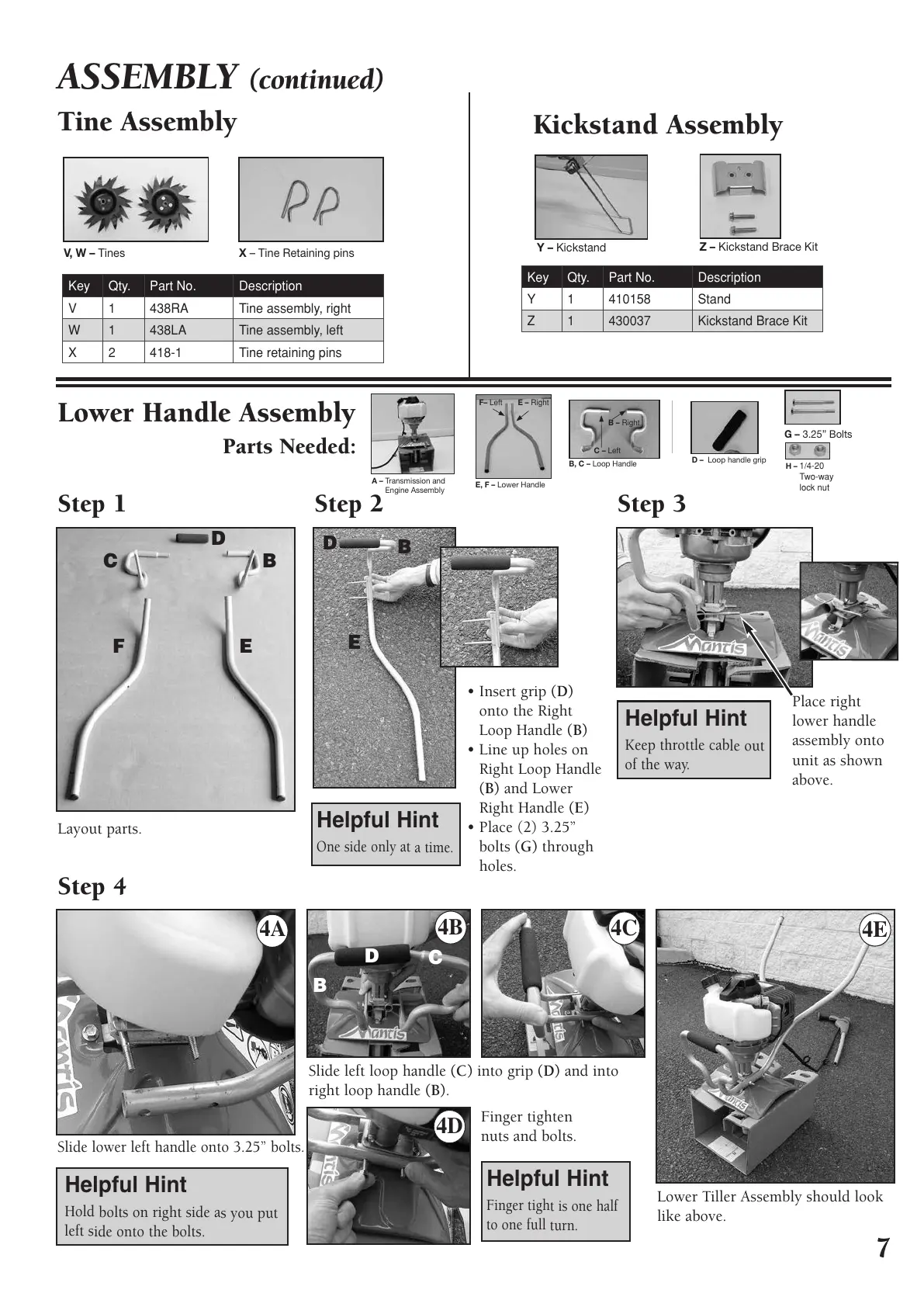
Lower Handle Assembly
Parts Needed:
Tine Assembly
Kickstand Assembly
Step 1
Layout parts.
Step 4
Slide lower left handle onto 3.25” bolts.
Lower Tiller Assembly should look
like above.
Finger tighten
nuts and bolts.
Slide left loop handle (C) into grip (D) and into
right loop handle (B).
Step 3
Place right
lower handle
assembly onto
unit as shown
above.
Step 2
• Insert grip (D)
onto the Right
Loop Handle (B)
• Line up holes on
Right Loop Handle
(B) and Lower
Right Handle (E)
• Place (2) 3.25”
bolts (G) through
holes.
One side only at a time.
Helpful Hint
Finger tight is one half
to one full turn.
Helpful Hint
Keep throttle cable out
of the way.
Helpful Hint
Hold bolts on right side as you put
left side onto the bolts.
Helpful Hint
D
D
B
B
C
B
C
D
FE
E
B, C – Loop Handle
B – Right
F
C – Left
1
A
K
K
1
D – Loop handle grip
I – C
H – 1/4-20
Two-way
lock nut
L
T
E
A
C
L
E, F –
Lower Handle
E – Right
B
F– Left
C
1
A
K
x
Z – Kickstand Brace Kit
Y – Kickstand
Key Qty. Part No. Description
Y1 410158 Stand
Z
1 430037 Kickstand Brace Kit
X – Tine Retaining pinsV, W – Tines
Key Qty. Part No. Description
V 1 438RA Tine assembly, right
W
1 438LA Tine assembly, left
X 2 418-1 Tine retaining pins
A – T
ransmission and
Engine Assembly
K
401775 Deluxe 2C Tiller-Cult Manual_Tiller Manual 8/8/11 8:07 AM Page 7
All manuals and user guides at all-guides.com
 Loading...