9
Tine Assembly
Upper Handle & Tube Assembly
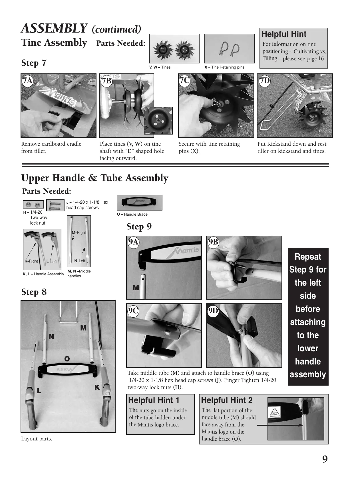
ASSEMBLY (continued)
Step 7
For information on tine
positioning – Cultivating vs.
Tilling – please see page 16
Helpful Hint
The nuts go on the inside
of the tube hidden under
the Mantis logo brace.
Helpful Hint 1
The flat portion of the
middle tube (M) should
face away from the
Mantis logo on the
handle brace (O).
Helpful Hint 2
Repeat
Step 9 for
the left
side
before
attaching
to the
lower
handle
assembly
Remove cardboard cradle
from tiller.
Take middle tube (M) and attach to handle brace (O) using
1/4-20 x 1-1/8 hex head cap screws (J). Finger Tighten 1/4-20
two-way lock nuts (H).
Step 8
Step 9
Layout parts.
Place tines (V, W) on tine
shaft with “D” shaped hole
facing outward.
Secure with tine retaining
pins (X).
Put Kickstand down and rest
tiller on kickstand and tines.
M
M
N
O
K
L
Parts Needed:
Parts Needed:
 Loading...