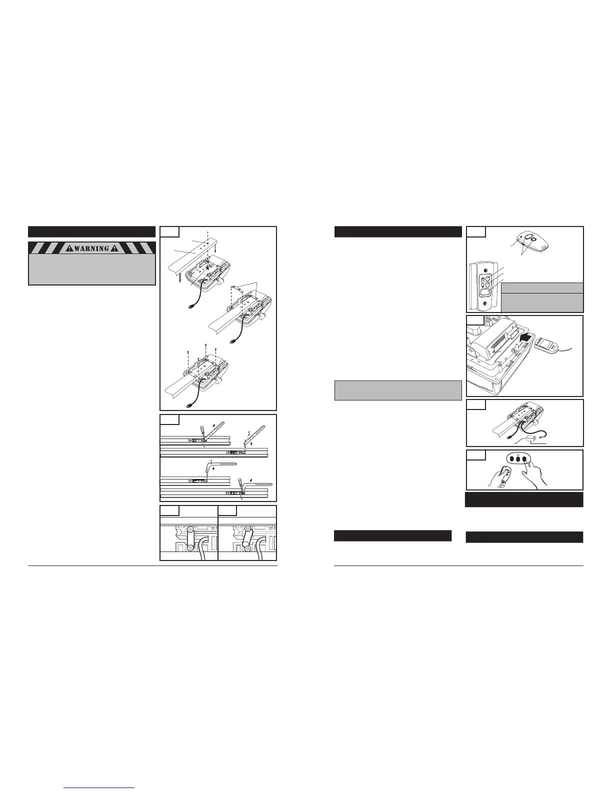
8-4. ATTACH RAIL TO OPERATOR HEAD
NOTE: Rail comes fully preassembled with straight door arm
already attached.
Unpack one-piece preassembled rail.
Leave straight door arm taped inside rail for safe and convenient
installation—it will be untaped and used later.
Position operator with control panel facing front of garage. Rest
operator head on cardboard or protective surface on floor so
opener does not get scratched. Chassis side of opener (with
motor shaft sticking out) facing up.
Position rail onto operator chassis by lining up rail sprocket
opening with motor head shaft (Fig. 17A). Make sure shaft
engages teeth inside rail sprocket. Press rail down firmly onto
shaft and opener chassis. DO NOT HAMMER.
Position 2 "C" rail clips over rail and onto chassis. Flanges on
"C" rail clips MUST fit into guide posts recesses (Fig. 17B).
Insert screws (6 x 14) through bracket holes and into chassis
holes, and tighten screws firmly to hold rail to head (Fig. 17C).
For sectional doors, proceed to step 8-5.
ADDITIONAL STEP FOR ONE-PIECE DOORS ONLY:
IMPORTANT NOTE: For installation on One-Piece Doors only,
the straight door arm that is factory installed onto the rail
must be replaced by the curved door arm supplied as part of
hardware in powerhead box. This must be done after
attaching rail to powerhead, before moving to step 8-5.
Turn rail and operator over so that open channel in rail
faces up.
Untape straight door arm that is secured inside rail.
Remove and save the two phillips head screws that are securing
the door arm pin and straight door arm (Fig. 18).
Lift arm and pin straight out of slot in trolley, and remove pin
from straight door arm.
Insert pin into short side of curved door arm as shown.
Orient arm so that long side extends away from trolley.
Carefully insert pin and door arm into slot in trolley.
Push pin into slot with door arm so pin is fully seated into trolley
slot. IMPORTANT: Pin must be straight and seated properly
into recessed area in trolley. See Figs. 18A and 18B.
Secure pin and curved arm with the two phillips screws which
were removed from trolley—DO NOT use any other screws.
Tighten screws firmly.
Turn rail and powerhead over so that open channel in rail faces
down. Now proceed to Step 8-5.
Fig. 18
10
27
A. Loosen Screws
B. Remove Pin
C. Feed Pin though Curved
Door Arm Hole
D. Reinsert Pin and Arm Firmly
and Squarely, Tighten Screws
Correctly seated pin.
Incorrectly seated pin.
Fig. 18A
Fig. 18B
When fastening the rail to the operator,
use only the screws provided. Use of any
other screws may result in operator falling
from ceiling and causing damage
to persons or property in the garage.
Fig. 17
B. Position “C” Rail Clip
over rail
A. Place Rail onto Chassis
Sprocket
Opening
Rail
Motor Head
Shaft
“C” Rail Clip
C. Secure “C” Rail Clip to Chassis
6x14 Screw
11. OPERATION OF YOUR OPERATOR
Fig. 47
Lock/Vacation Button
Light On/Off Button
Illuminated Door Pushbutton
B. Wall Control Panel
Your operator can be activated via any of the following, depending
on which accessories your opener system has:
Remote Control Transmitter
Wall Control Panel
Keyless Entry (optional accessory)
REMOTE CONTROL TRANSMITTER:
To open or close garage door, press and hold button (Transmitter
has an indicator light that will illuminate). See Fig. 47A. When
garage door begins to move, release button.
To stop garage door during travel, press and hold button until
door stops, then release button.
To resume garage door travel after stopping, press button again.
Door begins to move in the opposite direction.
14. HOMELINK
®
TRANSCEIVER
Before you can use your car’s HomeLink
®
device to open a
garage door you must transfer an active code from the
transmitter to the HomeLink
®
Universal transceiver.
(Reference - HomeLink
®
Manual) (See Fig. 49)
Indicator Light
Buttons
A. Transmitter
12. MODULAR ANTENNA
To replace modular antenna simply pull out existing module
located on the top of the chassis, and slide in the new one.
It will make a clicking sound when the receiver module is
locked into place. (See Fig. 48)
Fig. 49
Fig. 48
WALL CONTROL PANEL:
The Door Pushbutton will light when Wall Control properly
connected (if it does not light up, review section 8-11. “Install Wall
Control” on page 15 or refer to “Having a Problem” on page 33).
To open or close garage door, press and hold Illuminated Door
Pushbutton. See Fig. 48. When garage door begins to move,
release button.
To stop garage door during travel, press and hold button until
door stops, then release button.
To resume garage door travel after stopping it, press button
again. Door begins to move in the opposite direction.
The Light On / Off button can be used to turn lights on or off.
When using the light On / Off button, the automatic timer is ignored,
and the lights will remain on until the button is pressed again, or
until the operator is activated and the automatic timer begins again.
The Lock/Vacation button can be used to lock out all remote control
transmitters. The door can still be activated by wall control panel or
keyless entry system. Press and hold Lock/Vacation button for 2-3
seconds. Release button. Illuminated Door Pushbutton will flash
continuously while lock mode is active. To unlock opener, press and
hold Lock/Vacation button for 2-3 seconds.
OPERATOR LIGHTS:
The amount of time that the operator light(s) are “on” can be
adjusted. Please refer to level 5 menu 4 in the “Advanced Settings”
Lights will come on whenever operator is activated.
The default factory setting for the light to stay “on” is 4
minutes and 15 sec., or until the Light On / Off button on the
wall control panel is pressed, whichever is sooner.
Lights can be turned on and off manually as described under
operation of wall control panel.
Lights will flash when the operator senses an obstruction either
detected by the internal safety system or the photo eye sensors.
To stop lights from flashing, remove obstruction and operate
door normally. The fault light indicator will flash for the set
light time “on” factory default setting of 3 minutes maximum.
Important Note: If the vacation lock
mode is engaged.
By pressing and holding the light button
or the door activation button for one
second or longer will disengaged the
vacation lock mode.
NOTE: The Light On / Off button must be pressed twice,
in order to turn the operator light(s) off after a
door cycle (activation).
13*. LOCMATIC READY
Applicable for Locmatic Ready Operator
The control module harness on the same side as the operator
power cord shown on figure 48A is provided for connectivity
with the Locmatic System control module.
The Locmatic door
lock system is an optional accessory sold separately.
Fig. 48A
Door Lock Connection Leads
Control Module
 Loading...