11
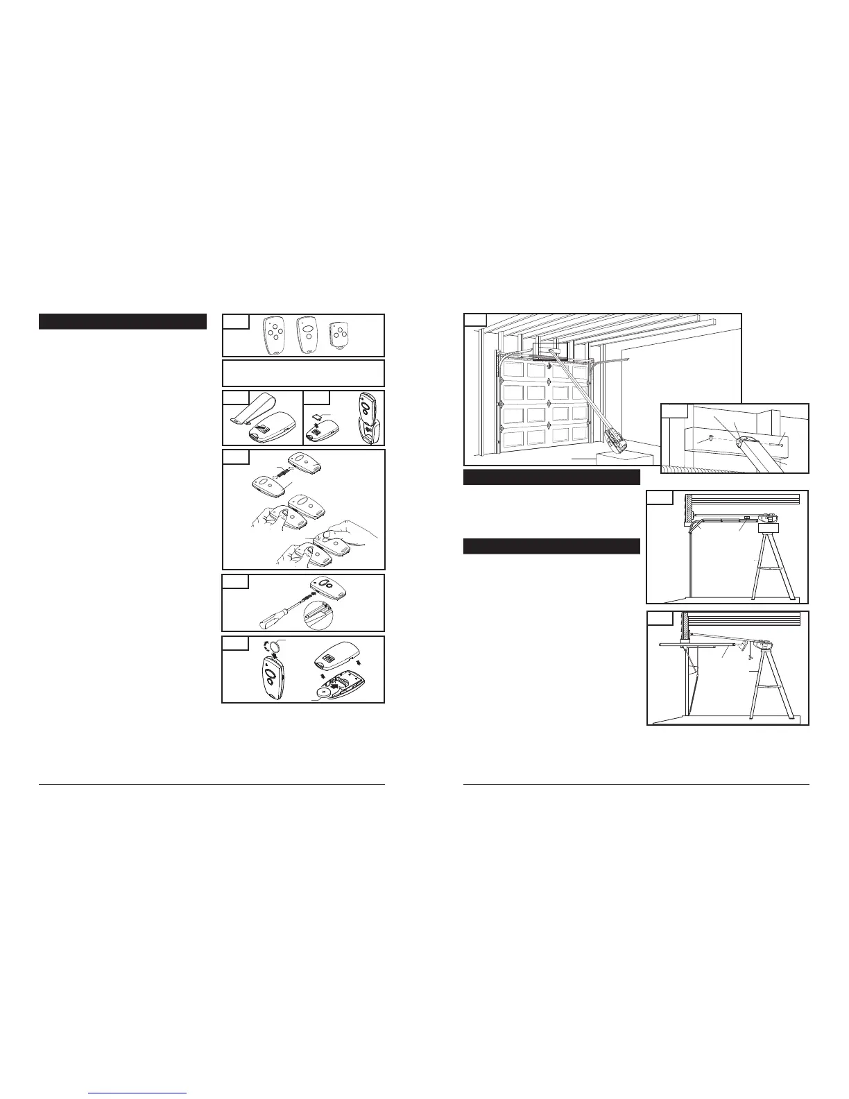
Fig. 44
Fig. 45
Fig. 46
Coin
Battery
26
8-5. ATTACH RAIL TO HEADER BRACKET
Support operator head slightly off the floor.
Lift the opposite end of the rail up to the header bracket.
Position rail end-stop within the openings in the header
bracket. Insert header clevis pin ( 1/4” dia.) through header
bracket and rail end-stop, then attach cotter ring to end
of pin. (See Fig. 19A)
8-6. POSITION OPERATOR FOR MOUNTING
Fig. 20
Once rail is attached to header bracket, support operator on ladder,
or use the assistance of another person to support operator high
enough so door can open without hitting the rail.
A. SECTIONAL DOORS AND ONE-PIECE DOORS WITH
TRACK:
Open garage door to fully opened position, and place a 2x4
laid flat between the door and the rail. See Fig.20. This provides
an easy method of ensuring the correct mounting height of
the opener.
B. ONE-PIECE DOORS WITHOUT TRACK:
Disconnect trolley by pulling down on emergency release knob.
Move trolley toward opener head.
Open door all the way so that it is parallel to the floor, or slightly
tilted toward the front of the garage. DOOR SHOULD NOT BE
TILTED TOWARD THE BACK OF GARAGE.
Position operator so that top of operator head is level with top
of opened door.
To check for correct mounting height, temporarily position
curved door arm as if connecting to door bracket. See Fig. 21.
The long side of the arm should be parallel to the floor when
door is fully opened. Raise or lower powerhead so that arm
will be parallel to floor.
Temporarily support head at this height, and prepare to mount
the operator to ceiling.
Door
2x4 Laid Flat
Stepladder
Door
Stepladder
Fig. 41
Fig. 42
Fig. 43
Visor Clip
Visor
Compartment
Cover
FCC Certified: This device complies with Part 15 of the FCC rules. Operation is subject to the following
two conditions: (1) this device may not cause harmful interference, and (2) this device must accept any
interference received, including interference that may cause undesired operation.
Changes or modifications not expressly approved by the party responsible
for compliance could void the user’s authority to operate the equipment.
10. TRANSMITTERS
TRANSMITTERS (Fig. 41):
A family of state-of-the-art transmitters, each transmitter is custom
encoded with installed battery. Offered in two styles to suit your
personal preference.
Mini (2-or 4-channel)
Micro (3-channel) with keyring attachment.
TRANSMITTER MOUNTING:
The transmitters can be conveniently mounted inside your
car using the visor clip or on the wall using the mounting plate.
Visor Clip (Fig. 42)
Snap visor clip into transmitter.
Affix assembly to visor.
NOTE: If you do not need the visor clip, install the visor
compartment cover.
Mounting Plate (Fig. 43)
Secure the mounting plate to area of preference using screw
and anchor.
Snap the visor compartment cover.
Slide the transmitter into the mounting plate, which will hold
it firmly in place.
MULTIPLE TRANSMITTERS (Fig. 44):
Each transmitter comes factory programmed with random codes.
2-channel transmitters have 2 different random codes, one per
button, 3-channel transmitters have 3 different random codes and
4-channel transmitters have 4 different random codes, one per
button. Transmitters that are purchased separately as accessories
have random codes that must be changed in order to match the
code of the “active” transmitter, which you are already using. Below
are instructions for transferring an active code from a button on one
transmitter to a button of your choice on another transmitter.
Connect the transmitter with active code to the new
transmitter using the programming connector. (Fig 44)
Press and hold the selected channel button on the transmitter
with the active code.
Press and hold the respective channel button on the new
transmitter. The light in the transmitter initially starts
blinking and then illuminates continuously after 1-2 sec.
Code transfer is completed.
Programming connector can be removed and both
transmitters can now be used to operate the same opener.
NOTE: For multi-button transmitters, be sure to carry out this
procedure for all the buttons you desire to use.
CHANGING THE CODE (Fig. 45):
The transmitter factory preset code can be changed as follows:
Insert the programming connector into transmitter terminal.
Short one of the outer pins of the programming connector
with the middle pin.
Press and hold the respective channel button. The light will
blink rapidly for approximately 5 sec. Release the button after
the light illuminates continuously. Code will change in
approximately 2 seconds.
Remove the programming connector.
Once the transmitter code is changed, the operator must be
recoded with the new transmitter code as described on the
initial system set up page 19.
NOTE: For multi-button transmitters, be sure to carry out this
procedure for all the buttons you desire to use.
BATTERY REPLACEMENT (Fig. 46):
Open the transmitter by using small coin.
Insert a 3V battery (type CR2032) as shown.
Close the transmitter.
NOTE: Replace batteries with same type only.
Fig. 21
Fig. 19
Operator Box
Header Bracket
Rail End-Stop
Cotter Ring
1/4 x 3-1/4"
Clevis Pin
Rail
Fig. 19A
Transmitter with
active Code
New Transmitter
Programming
Connector
Light blinks
 Loading...