9
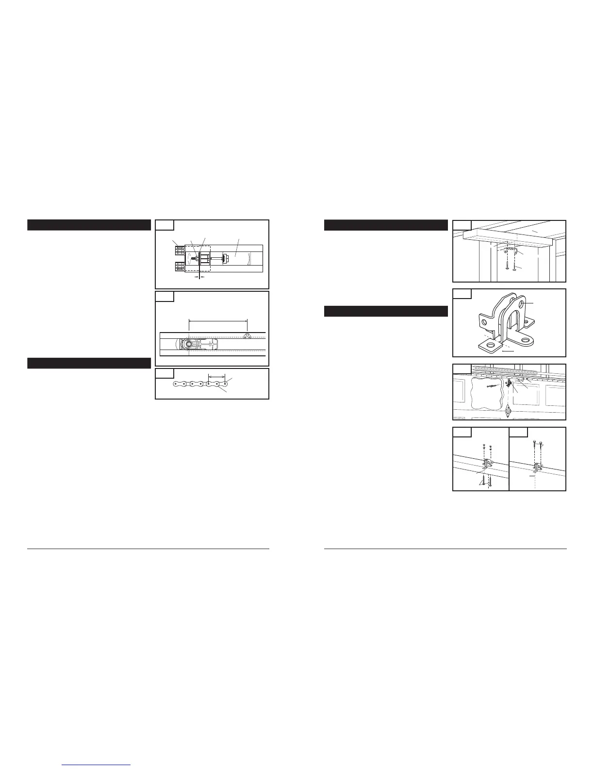
15. TENSION ADJUSTMENT
16. RAIL LENGTH ADJUSTMENT
Fig. 50
Proper Tension Adjustment
Your preassembled rail comes with the tension adjusted to factory
specifications. There should be no need for further adjustment.
However, if exposed or subjected to unusually harsh operating
conditions, the tension may need to be readjusted during the life
of the opener.
CHECK PROPER TENSION (Fig. 50):
Release trolley from belt or chain, then examine the setting of
the tension adjustment at the header end of the rail.
Proper tension is set when the tension nut is tightened just
enough so that the washer will be spaced approximately 1mm
or 3/64" from the stationary rail end-stop arch.
If the gap between the washer and the rail end-stop arch is too
big or too small, the tension needs to be adjusted.
ADJUST THE TENSION:
To increase the tension and tighten the belt or chain, turn the
tension nut clockwise with 7/16” wrench until the washer is
spaced properly from the rail end-stop arch. See Fig. 50.
Once the washer is spaced correctly, any additional tightening
will overtighten the belt or chain and may cause damage to the
system.
To loosen the tension, turn nut counterclockwise.
Reattach trolley.
Fig. 50A
960 mm (37-3/4")
Fig. 51
1"
FOR PROFESSIONAL INSTALLERS ONLY
If your particular installation calls for a shorter rail than the
standard length provided, it is possible to shorten the rail.
NOTE:
Shortening rail too much may result in door travel
length reduction and door not opening fully. This depends
on door size and configuration. Carefully plan all such
modifications before proceeding. THIS PROCEDURE SHOULD
BE PERFORMED ONLY BY A PROFESSIONAL INSTALLER FULLY
FAMILIAR WITH THIS TYPE OF OPENER SYSTEM.
TO SHORTEN BELT RAIL LENGTH:
Loosen belt tension as much as possible.
Remove screws from sprocket holder and rail end-stop.
Slide belt and all rail parts out of rail from header end. See rail
exploded view, Fig. 52 on p. 29, for disassembly details.
Measure and cut off excess rail from header end.
Using rail end-stop as a guide, mark and drill two 3/16" holes
on rail sides for rail end-stop screws.
Disassemble connector to expose free ends of belt.
Using the same measurement as the excess rail length, cut the
same amount off BOTH free ends of the belt.
Reassemble belt connector, and slide all rail parts into rail from
header end according to original assembly (Fig. 50 and
Fig. 50A).
Tension belt properly (Fig. 50).
Check rail for proper assembly and operation by manually
moving trolley from end to end and back to position per
Fig. 50A, with trolley connected to belt.
TO SHORTEN CHAIN RIAL LENGTH:
Loosen chain tension as much as possible.
Remove screws from sprocket holder and rail end-stop.
Slide chain and all rail parts out of rail from header end.
See rail exploded view, Fig. 53 on p. 29, for disassembly
details.
Measure and cut off excess rail from header end by 1”
increment only.
Using rail end-stop as a guide, mark and drill two 3/16"
holes on rail sides for rail end-stop screws.
Disassemble connector to expose free ends of chain.
Using the same measurement as the excess rail length,
remove the same amount off chain links and chain straps
from BOTH free ends of the chain (Fig. 51).
Reassemble two piece connector and slide chain and all
rail parts into rail from header end according to original
assembly (Fig. 50 and Fig. 50A).
Tension chain properly (Fig. 50).
Check rail for proper assembly and operation by manually
moving trolley from end to end and back to position per
Fig. 50A, with trolley connected to chain.
28
8-3. INSTALL DOOR BRACKET TO DOOR
Fig. 13
Pilot Hole
Ceiling
Header Bracket
Lag Screw
Fig. 12
Cut off for one-piece
door only
Pin Hole
Fig. 14
A. FOR SECTIONAL DOORS:
Wood Sectional Doors (Fig. 14)
Position door bracket (Fig. 13) along vertical center line of
door with pin hole facing top of the door and top edge of
the bracket 4” to 5” below top edge of the door, or roughly
at the same height as top rollers on the door.
Mark locations of securement holes through door bracket.
Drill two 1/4" holes through door for securement of door
bracket.
Insert carriage bolts (1/4” x 2”) from the outside through
door and bracket, then secure with lock washers and nuts
from the inside.
Tighten nuts firmly.
Metal Sectional Doors
Attach door bracket with two teck screws (provided) per Door
manufacturer recommendations.
B. FOR ONE-PIECE DOORS:
Before starting the installation of the door bracket, cut off
mounting leg from opposite side of pin hole.
One-Piece Doors with Exposed Frames (Fig. 15)
Position center of door bracket on the center line on the top
edge of door.
Mark the position where carriage bolts will go through
bracket, and drill two 1/4" holes through top frame of door.
Install carriage bolts from the bottom, through door frame
and bracket, and secure with lock washer and nut from top.
Tighten nuts firmly.
One-Piece Doors without Exposed Frames (Fig. 16)
For doors without exposed frames, use alternate method of
mounting door bracket.
Mark and drill two 3/16" pilot holes into top of frame, then
secure bracket with 5/16" x 1-5/8" lag screws (not provided).
8-2. INSTALL HEADER BRACKET (cont’d)
Insert 1/4-20 x 2”
Carriage Bolts
from outside of door
Lock Washer
1/4-20 Nut
Wood Sectional
Doors
Mark pilot holes location on header through header bracket
holes where lag screws will be inserted.
IMPORTANT: See Fig. 11 for which header bracket holes to
use.
Drill 3/16" pilot holes into header, and install bracket with lag
screws (5/16 x 1-3/4”) provided.
Tighten lag screws firmly.
NOTE: Follow the same procedure if header (shown in Fig.
11) runs vertically instead of horizontally and is the only
option for mounting header bracket to header wall. In case
of minimal clearance above the garage door, the header
bracket may be mounted to the ceiling. Follow the same
steps above to ensure a sound surface for mounting.
 Loading...